Pneumatic Valve Fail Position Explained: FO, FC and FL Selection Guide
Pneumatic valves are important control components in industrial automation systems and are widely used in oil and gas, chemical, power generation, water treatment, and other process industries.
By using pneumatic actuators as the driving force, pneumatic valves can achieve opening, closing, and flow control functions, making them essential equipment for ensuring safe and stable operation of industrial processes.
In practical applications, besides valve pressure rating, material selection, and control method, the fail position of a pneumatic valve is also a critical selection parameter.
When the air supply, power supply, or control signal fails, the pneumatic valve must move to a predefined safe position according to process safety requirements.
The most common fail positions include:
- FO (Fail Open)
- FC (Fail Close)
- FL (Fail Lock)
Selecting the correct fail position can effectively reduce operational risks and improve the safety and reliability of the entire industrial system.
Structure and Working Principle of Pneumatic Valves
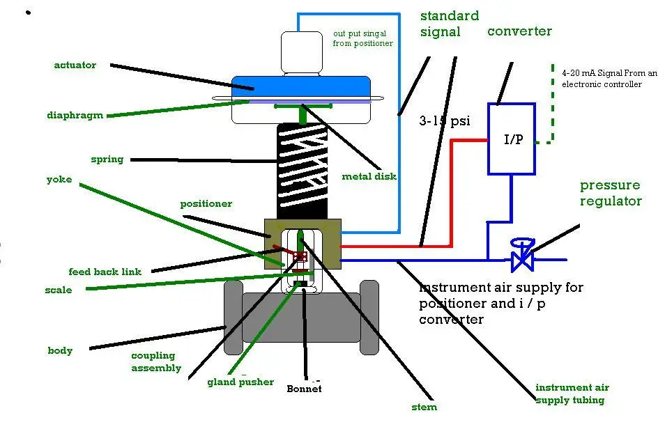
A pneumatic valve mainly consists of three parts:
- Pneumatic actuator;
- Valve body;
- Valve accessories.
The pneumatic actuator is the power component that controls valve movement. It usually includes:
- Springs;
- Piston or diaphragm;
- Actuator stem;
- Manual override mechanism.
A pneumatic valve uses clean compressed air as the power source. After receiving pneumatic or electrical signals, the actuator moves the valve stem and valve plug, changing the flow area between the valve plug and seat to achieve flow regulation or complete shut-off.
Common pneumatic valve accessories include:
- Solenoid valve;
- Valve positioner;
- Filter regulator;
- Limit switch.
Due to their fast response, high output torque, and ability to operate in harsh industrial environments, pneumatic valves are widely used in automated process control systems.
What Is Pneumatic Valve Fail Position?
The normal operation of pneumatic valves depends on stable air supply and control signals.
However, in industrial applications, failures may occur, including:
- Loss of air supply;
- Solenoid valve power failure;
- Control system failure;
- Signal interruption.
Under these conditions, the valve needs to move to a predefined safe position. This position is called the fail position.
The selection of fail position mainly depends on process safety requirements.
For example:
If closing the valve can prevent hazardous media from continuing to flow, a Fail Close (FC) design is usually selected.
If keeping the valve open can protect equipment from damage, a Fail Open (FO) design may be required.
If sudden valve movement may affect process stability, a Fail Lock (FL) design can be selected.
Difference Between FO, FC and FL Pneumatic Valve Fail Positions
| Type | Full Name | Meaning | Valve Position After Air Failure | Typical Applications |
|---|---|---|---|---|
| FC | Fail Close | Fail to close | Valve moves to closed position | Oil & gas, fuel systems, hazardous media isolation |
| FO | Fail Open | Fail to open | Valve moves to open position | Cooling systems, protection systems, flow-maintaining applications |
| FL | Fail Lock | Fail to lock | Valve remains at current position | Continuous processes, precision control systems |
FC (Fail Close)
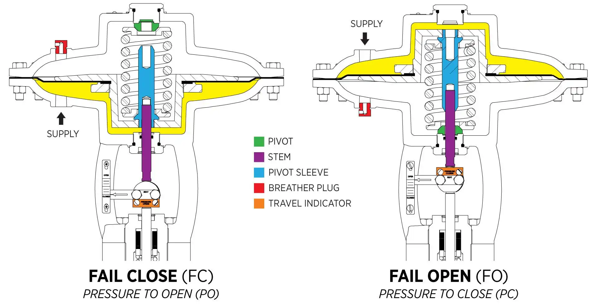
FC means that the valve automatically moves to the closed position when the air supply or control signal fails.
This fail mode is commonly used in systems where stopping media flow is required for safety.
For example, in natural gas, fuel, and hazardous chemical pipelines, closing the valve during abnormal conditions can quickly isolate the media supply and improve system safety.
FO (Fail Open)
FO means that the valve automatically moves to the open position when the air supply fails.
This design is usually applied where maintaining flow is necessary to protect equipment or prevent process interruption.
For example, in cooling water systems, closing the valve may cause equipment overheating, so a Fail Open design is often selected.
FL (Fail Lock)
FL means that the valve remains in its current position when the air supply or control signal fails.
This design is suitable for continuous production processes where sudden valve movement may affect process parameters.
For example, some precision flow control systems use Fail Lock designs to minimize production fluctuations.
How to Select the Correct Fail Position for Pneumatic Valves?
There is no universal answer when selecting FO, FC, or FL. The correct choice depends on the process conditions and safety requirements.
In oil and gas applications, emergency shutdown valves (ESD valves) often use FC designs because closing the valve can quickly isolate hazardous media during emergency situations.
In cooling or equipment protection systems, FO may be selected because maintaining flow is necessary to prevent equipment damage.
For continuous production systems, FL may be preferred because maintaining the current valve position helps avoid sudden process changes.
Therefore, fail position selection should consider:
- Media hazard level;
- Process safety analysis;
- Equipment protection requirements;
- Control system logic.
Common Operating Problems of Pneumatic Valves

During long-term operation, pneumatic valves may experience performance issues caused by air supply conditions, installation environment, or internal component wear.
Valve leakage is usually related to wear of the valve plug, valve seat, or sealing surfaces. Foreign particles inside the valve may also prevent complete closure. Regular inspection of sealing conditions and replacement of damaged components can effectively reduce leakage.
Unstable valve operation is often caused by unstable air pressure, positioner failure, or abnormal control signals. A stable air supply and proper positioner adjustment are essential for accurate valve operation.
Valve vibration may result from several factors, including friction between the valve plug and seat, unstable installation, improper valve selection, or incorrect flow direction. When vibration occurs, the valve installation and operating conditions should be carefully checked.
Slow valve movement is usually related to stem friction, improper packing conditions, actuator problems, or internal contamination. Inspecting the valve stem, adjusting packing, and cleaning internal components can improve operating performance.
When a pneumatic valve does not operate at all, the air supply system, solenoid valve, positioner, and control signals should be checked to confirm that the actuator receives the correct operating command.
Applications of Pneumatic Valves in Industry
Due to their fast response, high reliability, and excellent automation capabilities, pneumatic valves are widely used in:
- Oil and gas industries;
- Petrochemical plants;
- Power generation systems;
- Water treatment projects;
- Industrial automation systems.
Especially in oil and gas projects, pneumatic actuated valves are commonly used for:
- Emergency shutdown valves (ESD valves);
- Pipeline control valves;
- Pressure control systems;
- Automated interlock systems.
Conclusion
The fail position of pneumatic valves (FO, FC, and FL) is an important parameter during valve selection.
Choosing the correct Fail Open, Fail Close, or Fail Lock mode ensures that the valve moves to a safe condition during abnormal situations and improves the reliability of industrial processes.
In practical projects, fail position selection should be based on media characteristics, process requirements, safety standards, and control system design.
By selecting the appropriate pneumatic valve fail mode, industrial facilities can improve operational safety, reduce risks, and ensure reliable long-term operation.
FAQ
Q1: What does FC mean on a pneumatic valve?
FC means Fail Close. When the air supply or control signal fails, the pneumatic valve automatically moves to the closed position.
Q2: What is the difference between FO and FC pneumatic valves?
FO valves open when the air supply fails, while FC valves close when the air supply fails. The correct selection depends on the safety requirements of the process system.
Q3: Which fail position is commonly used for oil and gas valves?
In oil and gas applications, FC is commonly selected for emergency shutdown valves because closing the valve can quickly isolate hazardous media and improve system safety.

Get professional pre-sales technical consultation and valve selection services, customized solution services.

About CEPAI
Popular Blogs