How to Select a Steam Pressure Reducing Valve? Selection Guide and Pressure Reducing Station Design Considerations
In industrial production processes, steam is one of the most widely used heat transfer media. It is commonly applied in industries such as oil and gas, petrochemical, power generation, food processing, pharmaceutical manufacturing, textile, and paper production.
A basic principle of industrial steam systems is "high-pressure transmission and low-pressure utilization." Steam is usually generated at a relatively high pressure by boilers and then reduced to a suitable pressure level before being supplied to different process equipment.
Therefore, steam pressure reducing valves, also known as steam PRVs or steam pressure regulators, play an essential role in industrial steam distribution systems.
The main function of a steam pressure reducing valve is to reduce upstream steam pressure and maintain a stable downstream pressure, ensuring that heating equipment operates safely and efficiently.
However, many problems commonly occur in practical applications, including:
- Safety valve lifting caused by excessive downstream pressure;
- Unstable heating performance due to pressure fluctuation;
- Frequent valve adjustment leading to premature wear;
- Cavitation, erosion, and sealing failure inside the valve.
In many cases, these problems are not caused by product quality, but by incorrect valve selection or improper pressure reducing station design.
Therefore, selecting the correct steam pressure reducing valve requires a comprehensive understanding of operating pressure, steam flow, pressure ratio, installation conditions, and system requirements.
This article explains the key factors that should be considered when selecting a steam pressure reducing valve and designing a reliable steam pressure reducing station.
Key Factors to Consider When Selecting a Steam Pressure Reducing Valve

A steam pressure reducing valve should not be selected simply according to pipeline size.
The correct selection requires consideration of several important parameters, including upstream pressure, downstream pressure, steam flow rate, steam quality, installation conditions, and safety requirements.
Upstream and Downstream Steam Pressure
The two most important pressure parameters are:
- Upstream pressure (primary pressure);
- Downstream pressure (secondary pressure).
The upstream pressure refers to the steam pressure before the reducing valve.
For example:
Boiler steam pressure:
10 barg
The downstream pressure refers to the required pressure after pressure reduction.
For example:
Process equipment requirement:
4 barg
The pressure difference between these two values determines the working condition of the reducing valve.
A large pressure reduction ratio creates a more demanding operating environment and may require special consideration, such as multi-stage pressure reduction.
Steam Flow Rate
Steam flow rate is another critical parameter for valve sizing.
The actual steam demand should include:
- Minimum flow rate;
- Normal operating flow rate;
- Maximum flow rate.
A common mistake is selecting the valve only according to the maximum steam consumption.
This may result in an oversized pressure reducing valve that operates at very small openings during normal operation.
When the valve operates at an extremely small opening:
- Pressure control becomes unstable;
- Valve adjustment becomes frequent;
- Internal components experience increased wear;
- Service life is reduced.
Therefore, the pressure reducing valve should be sized according to the actual operating range rather than only the maximum flow requirement.
Condensate Control in Steam Pressure Reducing Systems
Condensate is one of the most important factors affecting steam valve performance.
During steam transportation, heat loss causes part of the steam to condense into water.
If condensate is not removed effectively, it may cause:
- Water hammer;
- Valve seat erosion;
- Seal damage;
- Failure of pressure regulation.
Therefore, proper condensate management is essential in a steam pressure reducing station.
A steam separator is recommended before the pressure reducing valve to remove entrained water droplets and improve steam quality.
A float-type steam trap assembly is usually preferred for draining condensate from the system.
Thermodynamic steam traps are generally not recommended for this application because their discharge characteristics may not provide sufficient stability for pressure reducing stations.
If condensate enters the pressure reducing valve, severe water hammer may damage internal components, including:
- Diaphragms;
- Valve seats;
- Pilot valves.
This may eventually lead to pressure control failure.
Installation of Filters and Protection Against Impurities
Steam pipelines often contain impurities such as:
- Welding slag;
- Rust particles;
- Scale deposits.
If these contaminants enter the pressure reducing valve, they may block the pilot system or damage the sealing surfaces.
Therefore, a filter should always be installed upstream of the steam pressure reducing valve.
A Y-type strainer with a 100-mesh filter screen is commonly recommended.
The filter should be installed correctly to avoid condensate accumulation and reduce the risk of water hammer.
Installation Distance and Straight Pipe Requirements
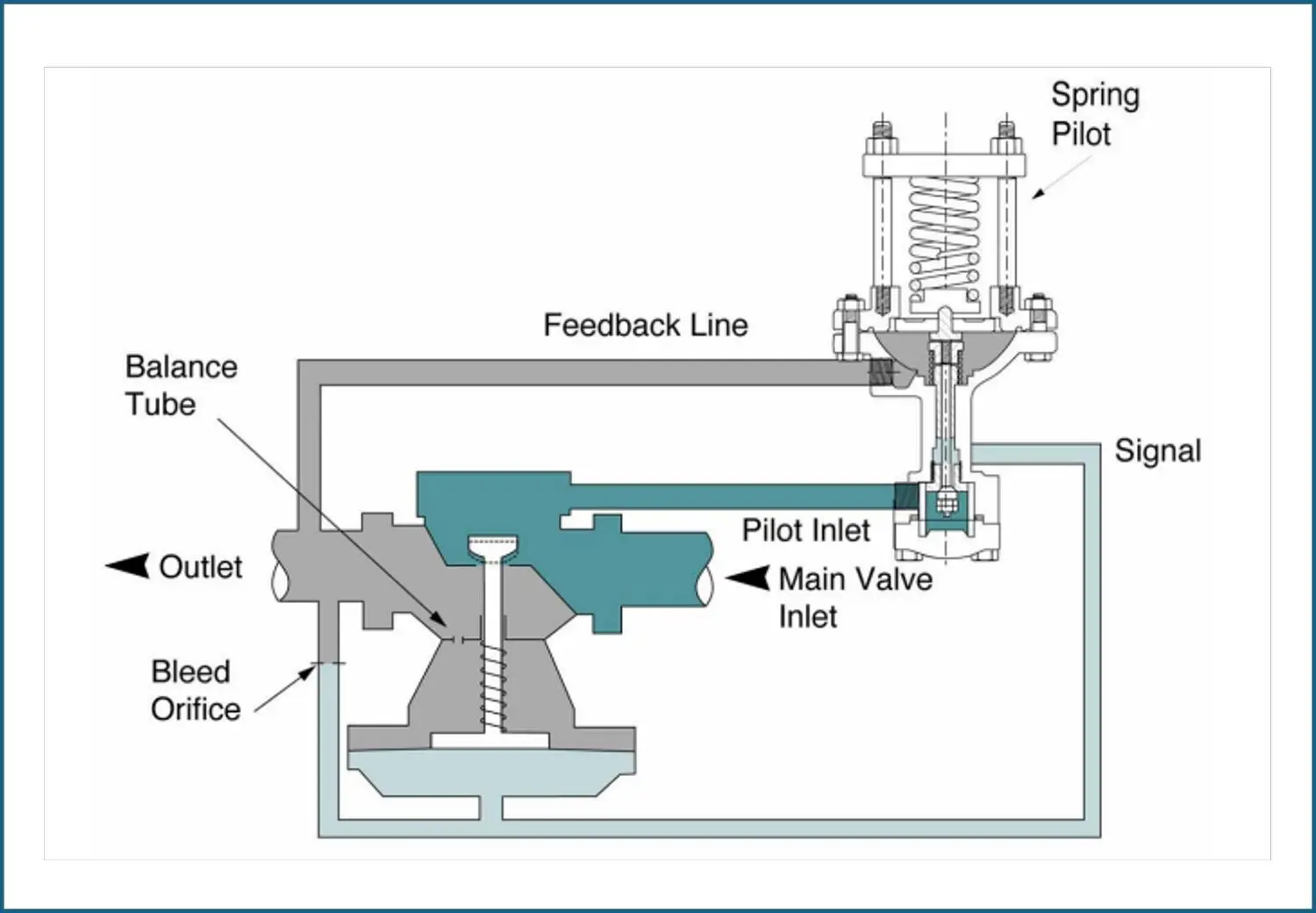
A pressure reducing valve is not an independent component. It is part of a complete pressure reducing station.
The installation arrangement directly affects pressure stability and valve service life.
The distance between the pressure reducing valve and other components should be carefully considered, including:
- Isolation valves;
- Pressure gauges;
- Safety valves;
- Control valves;
- Pneumatic valves.
A sufficient downstream straight pipe length is required because the steam flow needs space to stabilize after pressure reduction.
Generally:
The downstream straight pipe length should be at least:
15 times the pipe diameter (15D)
A longer distance, usually around 1 meter or more, is recommended when space allows.
For pneumatic valves installed near the pressure reducing valve, such as pneumatic ball valves, shut-off valves, or control valves, the recommended distance is:
30 times the pipe diameter (30D)
or at least 1 meter.
Insufficient installation distance may cause:
- Pressure fluctuation;
- Unstable control;
- Frequent valve movement.
Material Selection for Hygienic Applications
For applications requiring high cleanliness, such as:
- Food processing;
- Pharmaceutical production;
- Biotechnology industries;
material selection becomes very important.
A stainless steel steam pressure reducing valve is usually recommended.
Typical requirements include:
- Stainless steel valve body;
- Hygienic sealing materials;
- Suitable surface finish;
- Compliance with sanitary requirements.
Safety Valve Arrangement
A safety valve is normally installed downstream of the steam pressure reducing valve to protect equipment from overpressure caused by valve failure.
The safety valve setting pressure should not be too close to the pressure reducing valve outlet pressure.
For example:
If the downstream pressure setting is:
4 barg
The safety valve setting may be:
Approximately 5 barg.
If the setting pressure is too close, normal pressure fluctuations may cause unnecessary safety valve lifting.
The safety valve should generally be installed at a reasonable distance downstream of the pressure reducing valve, commonly around 1 meter or more.
The discharge piping should lead to a safe location and should not be excessively long, ensuring rapid pressure release during overpressure conditions.
How to Select the Correct Type of Steam Pressure Reducing Valve?
After confirming the basic operating conditions, the next important step is selecting the appropriate type of steam pressure reducing valve.
The main types used in industrial steam systems include:
- Direct-acting pressure reducing valves;
- Pilot-operated pressure reducing valves.
The correct selection depends mainly on steam flow, pressure stability requirements, upstream pressure fluctuations, and downstream load changes.
Direct-Acting Steam Pressure Reducing Valve
A direct-acting pressure reducing valve has a relatively simple structure.
The downstream pressure directly acts on the diaphragm or sensing element, which controls the opening of the valve.
This type is suitable for applications where:
- Steam flow is relatively small;
- Upstream pressure is stable;
- Downstream load changes are limited;
- Pressure accuracy requirements are not extremely strict.
Typical applications include:
- Small steam heating equipment;
- Food processing machines;
- Packaging equipment;
- Local steam supply systems.
The main advantages of direct-acting pressure reducing valves are:
- Simple structure;
- Compact design;
- Easy maintenance;
- Lower initial cost.
However, compared with pilot-operated valves, direct-acting valves generally have lower pressure stability and are more sensitive to load fluctuations.
Pilot-Operated Steam Pressure Reducing Valve
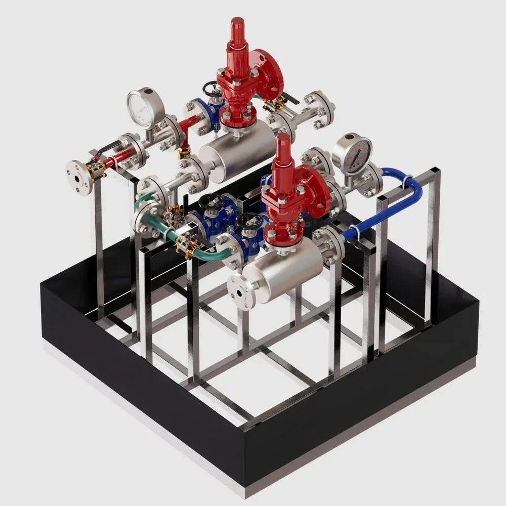
For most industrial steam applications, pilot-operated pressure reducing valves are the preferred choice.
A pilot-operated valve uses a small pilot valve to control the main valve. The pilot system amplifies the sensing force, allowing the valve to maintain more stable downstream pressure.
Pilot-operated pressure reducing valves are suitable for demanding applications, including:
- Large steam systems;
- High pressure reduction ratios;
- Significant upstream pressure fluctuations;
- Large variations in downstream steam demand.
Their advantages include:
- Better pressure stability;
- Higher flow capacity;
- Improved response to load changes;
- Longer service life under industrial conditions.
For general applications:
- DN15–DN50: diaphragm pilot-operated type is commonly recommended;
- DN65 and above: piston pilot-operated type is usually preferred.
Why Should Steam Pressure Reducing Valves Be Selected Individually?
One of the most common mistakes in steam system design is selecting the pressure reducing valve only according to pipeline diameter.
For example:
A DN100 steam pipeline does not necessarily require a DN100 pressure reducing valve.
The valve size should be calculated based on:
- Upstream pressure;
- Downstream pressure;
- Steam flow rate;
- Pressure reduction ratio;
- Required control accuracy.
In many properly designed systems, the pressure reducing valve size may be one or two sizes smaller than the main pipeline size.
This is completely normal.
The purpose is to ensure that the valve operates within an effective control range.
Why Oversized Steam Pressure Reducing Valves Cause Problems
A pressure reducing valve should normally operate at an opening range of approximately:
50%–80%
This range provides the best balance between:
- Pressure stability;
- Adjustment capability;
- Valve life;
- Energy efficiency.
If the valve is oversized, it will operate at very small openings most of the time.
This creates several problems.
Increased Risk of Flashing and Erosion
During steam pressure reduction, the pressure drops rapidly through the throttling area.
When the valve opening is extremely small, steam velocity becomes very high.
The high-speed steam flow may cause:
- Flashing;
- Cavitation;
- Valve seat erosion;
- Damage to sealing surfaces.
Over time, the valve seat and disc may develop:
- Pitting;
- Honeycomb-like damage;
- Leakage.
Unstable Pressure Control
When the valve operates near the closed position, even a very small movement of the valve plug can create a large change in steam flow.
As a result:
- Downstream pressure fluctuates;
- The valve adjusts frequently;
- Control accuracy decreases.
Frequent movement also increases wear on:
- Valve stem;
- Pilot valve;
- Sealing components.
Reduced Service Life
An oversized pressure reducing valve increases:
- Initial purchase cost;
- Operating instability;
- Maintenance frequency.
Therefore, selecting a larger valve does not necessarily improve performance.
In many cases, a correctly sized smaller valve provides better pressure control and longer service life.
Problems Caused by an Undersized Pressure Reducing Valve
Selecting a valve that is too small creates the opposite problem.
When the steam demand exceeds the valve capacity:
The pressure reducing valve may remain fully open but still cannot provide sufficient steam flow.
This may result in:
- Insufficient downstream pressure;
- Reduced heating performance;
- Longer production cycles;
- Reduced equipment efficiency.
Continuous operation at full opening may also accelerate:
- Valve seat erosion;
- Mechanical fatigue;
- Internal component damage.
Therefore, the correct principle is:
Do not select a pressure reducing valve that is too large or too small. Select according to the actual operating conditions.
When Is a Series Pressure Reducing Station Required?
A single pressure reducing valve is not always suitable for applications with a very large pressure reduction ratio.
For example:
Upstream pressure:
20 barg
↓
Required downstream pressure:
2 barg
This represents a large pressure reduction.
In such cases, a two-stage pressure reducing system may be required.
Generally:
Pilot-operated pressure reducing valves:
- Pressure reduction ratio ≈ 10:1
- Direct-acting pressure reducing valves:
- Pressure reduction ratio ≈ 20:1
When the pressure reduction range is extremely large, especially when the pressure difference exceeds approximately 8 bar, a series pressure reducing arrangement should be considered.
Important Considerations for Series Pressure Reducing Stations
A series pressure reducing station consists of:
First-stage pressure reducing valve
↓
Second-stage pressure reducing valve
For example:
20 barg
↓
8 barg
↓
2 barg
Installation Distance Between Two Valves
The distance between the two pressure reducing valves must be sufficient to allow the steam flow to stabilize.
Recommended distance:
At least:
30 times the valve diameter (30D)
or:
0.5–1 meter minimum.
If the distance is too short:
- Pressure fluctuations may occur;
- The second valve may adjust frequently;
- Noise and vibration may increase.
Avoiding Secondary Valve Damage
If the first-stage pressure reducing valve fails or becomes unstable, the inlet pressure of the second-stage valve may change rapidly.
The second-stage valve then has to continuously adjust to maintain downstream pressure.
This can cause:
- Pilot valve wear;
- Diaphragm fatigue;
- Mechanical damage;
- Shortened service life.
Therefore, the first-stage pressure reducing valve must operate reliably.
If it cannot maintain stable pressure, it should be repaired or replaced.
When Is a Parallel Pressure Reducing Station Required?
A parallel pressure reducing station consists of two or more pressure reducing valves installed in parallel.
It is commonly used when:
- Steam flow is very large;
- Maximum and minimum flow rates vary significantly;
- Continuous operation without shutdown is required.
A parallel arrangement should be considered when:
Very Large Steam Consumption
Large industrial facilities often experience high steam demand during full production operation.
Using multiple smaller valves allows each valve to operate within a stable control range.
Large Flow Variation
If:
Maximum flow ÷ Minimum flow > 10:1
A single large pressure reducing valve may not provide stable control.
A parallel system allows one valve to handle low demand while multiple valves operate during peak demand.
No Shutdown Is Allowed
For critical processes such as:
- Petrochemical plants;
- Power generation facilities;
- Pharmaceutical production;
a parallel system can provide:
- One valve operating;
- One valve standby.
This improves system reliability and maintenance flexibility.
Advantages of Parallel Pressure Reducing Stations
When steam demand is high:
Both pressure reducing valves operate together.
Each valve works within an appropriate opening range.
When steam demand decreases:
One valve can automatically close while the other continues operation.
This provides:
- More stable downstream pressure;
- Better control at low flow conditions;
- Longer valve service life;
- Reduced maintenance requirements.
If only one oversized valve is installed, the valve may operate at a very small opening during low demand periods.
This leads to:
- Pressure fluctuation;
- Poor control performance;
- Increased valve wear.
Other Important Steam Pressure Reducing Station Design Considerations
Condensate Drainage Before and After the Valve
Condensate drainage is essential around the pressure reducing valve.
A steam separator and drain system should normally be installed before the valve.
The recommended arrangement includes:
- Steam separator;
- Float-type steam trap group.
Condensate should be removed within approximately 3 meters before and after the pressure reducing valve.
Bypass Valve Arrangement
A bypass line is commonly installed for:
- Maintenance;
- Emergency operation;
- Temporary steam supply.
The bypass should preferably be installed on the same horizontal plane as the pressure reducing valve.
If vertical installation is unavoidable:
The bypass valve should be located above the pressure reducing valve.
Installing the bypass below the valve may allow condensate and contaminants to accumulate.
These contaminants may enter the pressure reducing valve and cause:
- Stem sticking;
- Pilot leakage;
- Overpressure problems.
For steam applications, a bellows sealed globe valve is often recommended as the bypass valve because of its reliable sealing performance.
Pipe Reduction Design
The pressure reducing valve size is often smaller than the main pipeline size. Proper reducers should be used. Eccentric reducers are generally preferred over concentric reducers. The reason is that eccentric reducers help prevent condensate accumulation and improve drainage.
Separate Condensate Recovery Systems
High-pressure condensate before the pressure reducing valve and low-pressure condensate after the valve should not be connected directly together.
Otherwise, downstream condensate may flow backward into the pressure reducing valve.
This can cause:
- Water hammer;
- Valve failure;
- Loss of pressure control.
Separate condensate recovery systems should be considered.
Steam Pressure Reducing Valve Selection Checklist
When requesting a quotation from a manufacturer, the following information should be provided:
| Parameter | Required Information |
|---|---|
| Medium | Saturated steam / Superheated steam |
| Upstream pressure | Steam inlet pressure |
| Downstream pressure | Required outlet pressure |
| Flow rate | Minimum / Normal / Maximum flow |
| Temperature | Steam temperature |
| Pipe size | Pipeline diameter |
| Connection | Flange / Thread |
| Material requirement | Carbon steel / Stainless steel |
| Installation environment | Indoor / Outdoor |
| Pressure stability requirement | Control accuracy requirements |
Conclusion
Selecting a steam pressure reducing valve is not simply a matter of matching the valve size with the pipeline diameter.
A reliable steam pressure reducing system requires comprehensive consideration of:
- Steam pressure;
- Flow variation;
- Pressure reduction ratio;
- Valve structure;
- Condensate management;
- Filtration;
- Installation distance;
- Safety protection.
For small and stable applications, direct-acting pressure reducing valves may provide a simple and economical solution. For most industrial steam systems, especially applications with fluctuating pressure and changing steam demand, pilot-operated steam pressure reducing valves provide better control performance and longer service life. A properly designed steam pressure reducing station improves pressure stability, reduces valve failure, protects downstream equipment, and ensures safe and efficient operation of industrial steam systems.
FAQ
Why does a steam pressure reducing valve cause pressure fluctuation?
Common causes include:
- Oversized valve selection;
- Operation at very small opening;
- Large changes in steam demand;
- Condensate entering the valve;
- Blocked filter;
- Incorrect valve type selection.
Should a steam pressure reducing valve be selected larger or smaller?
Neither. The correct size should be calculated based on actual steam flow and pressure conditions. An oversized valve causes unstable pressure control, while an undersized valve cannot provide sufficient flow. The ideal operating range is usually around 50%–80% opening.
Why is a steam separator required before a pressure reducing valve?
Because water droplets carried by wet steam can cause:
- Erosion;
- Cavitation;
- Water hammer.
A steam separator improves steam quality and protects the pressure reducing valve.

Get professional pre-sales technical consultation and valve selection services, customized solution services.

About CEPAI
Popular Blogs