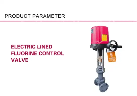
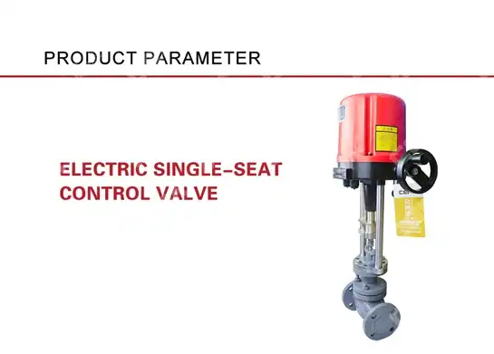
How to Properly Wire and Set Up Your Electric Control Valve?
Properly wiring and setting up an Electric Control Valve is crucial for ensuring optimal performance, longevity, and safety in your industrial automation system. These sophisticated flow control devices require precise installation and configuration to deliver the high-precision control capabilities they're designed for. In this comprehensive guide, we'll explore the essential steps, best practices, and technical considerations for successfully implementing Electric Control Valves in various industrial applications. Whether you're installing a new system or upgrading existing equipment, these expert insights will help you maximize the efficiency and reliability of your fluid control operations.

Understanding Electric Control Valve Components and Wiring Requirements
Electric Control Valves represent a sophisticated integration of mechanical, electrical, and control systems. Before beginning the installation process, it's essential to understand the various components and their specific wiring requirements to ensure proper functionality and prevent potential damage.
Power Supply Specifications and Requirements
The foundation of any Electric Control Valve installation begins with proper power supply configuration. Electric Control Valves typically operate on standard voltage supplies of 24V DC, 110V AC, or 220V AC, depending on the specific model and manufacturer specifications. When wiring your Electric Control Valve, it's crucial to verify the exact power requirements from the manufacturer's documentation to prevent electrical damage. Power fluctuations can significantly impact valve performance, so implementing surge protection devices and stabilized power supplies is highly recommended, especially in environments prone to electrical instability. Additionally, proper grounding according to local electrical codes is essential for safety and to prevent electromagnetic interference that could affect the precision of the Electric Control Valve's positioning system. Many industrial applications utilize uninterruptible power supplies (UPS) to ensure continuous operation during brief power outages, which is particularly important for critical process applications where flow control must be maintained at all times.
Control Signal Wiring and Configuration
Electric Control Valves require precise control signals to accurately position the valve according to process requirements. Modern Electric Control Valves typically accept standard industrial control signals, including 4-20mA, 0-10V DC, or digital communication protocols such as HART, Foundation Fieldbus, or Profibus. When installing the control signal wiring, it's essential to use shielded cables with appropriate gauge ratings based on the distance between the control system and the valve actuator. The shield should be properly grounded at one end only to prevent ground loops that could introduce signal noise. Signal wires should be routed separately from power cables to minimize electromagnetic interference, with a minimum separation distance of 30cm recommended for parallel runs. For analog signals, verify the polarity of the connections as reversed polarity will prevent proper operation of the Electric Control Valve. Most modern valve positioners include calibration functions that allow for scaling and characterization of the control signal to achieve optimal flow characteristics based on the specific application requirements, enabling precise flow control across the entire operating range.
Feedback Signal and Limit Switch Connections
Advanced Electric Control Valves incorporate position feedback systems that provide real-time information about valve position to the control system. These feedback signals are critical for closed-loop control and for monitoring valve performance over time. Position feedback is typically provided via a 4-20mA signal, potentiometer output, or digital communications. When wiring feedback circuits, use shielded twisted-pair cables similar to those used for control signals, and maintain appropriate separation from power cables to avoid interference. Many Electric Control Valves also incorporate limit switches that provide discrete signals when the valve reaches fully open or fully closed positions, or at predetermined intermediate positions. These limit switches often require separate wiring and may use different voltage levels than the main control circuits. Proper configuration of these limit switches is essential for processes that require end-position confirmation or for safety interlocks. Modern intelligent valve positioners may also provide diagnostic information through the feedback circuit, including cycle counts, total travel distance, and abnormal operation conditions, which can be valuable for predictive maintenance programs and for optimizing the performance of the Electric Control Valve throughout its operational life.

Installation Best Practices for Electric Control Valves
Proper installation is critical for ensuring the reliability and longevity of Electric Control Valves. Following industry best practices during the installation phase can prevent many common issues and minimize maintenance requirements over the valve's lifespan.
Mechanical Installation and Mounting Considerations
The mechanical installation of an Electric Control Valve requires careful attention to detail to ensure proper alignment and support. Before installation, inspect the pipeline for cleanliness; debris or welding slag can damage valve seats and sealing surfaces of the Electric Control Valve upon startup. The valve should be installed in an orientation that allows for proper actuator operation and easy access for maintenance personnel. Most Electric Control Valves include flow direction indicators that must be aligned with the process flow to ensure proper performance. Adequate support for both the valve body and actuator is essential, especially for larger valves, to prevent stress on the pipeline and valve components. When installing flanged Electric Control Valves, use appropriate gaskets and tighten bolts in a cross-pattern to ensure even compression and prevent leakage. The mounting location should also consider environmental factors such as temperature extremes, humidity, and exposure to corrosive substances that could affect the performance and lifespan of the Electric Control Valve. For outdoor installations, proper protection against the elements is necessary, which may include weather shields, insulation, or heated enclosures depending on the climate conditions. Always verify that the installed valve has sufficient clearance for the full range of actuator movement and that manual override mechanisms, if present, are accessible for emergency operation.
Control System Integration and Communication Setup
Modern Electric Control Valves must be effectively integrated into broader control systems to deliver their full value. The integration process begins with establishing proper communication between the valve positioner and the control system. For analog control systems, this typically involves verifying signal ranges and ensuring proper scaling in the control software. For digital communication protocols like HART, Foundation Fieldbus, or Profibus, additional configuration steps are necessary, including setting device addresses, communication parameters, and network termination. Many Electric Control Valves now come with intelligent positioners that require initial configuration using specialized software or handheld communicators. This setup process typically includes defining valve characteristics, setting control parameters, and configuring alarm conditions. When integrating Electric Control Valves into distributed control systems (DCS) or programmable logic controllers (PLCs), it's important to develop appropriate control strategies that account for the valve's specific response characteristics. This may include implementing advanced control algorithms such as adaptive control or model predictive control to optimize performance. System integration should also include proper documentation of all configuration parameters, wiring diagrams, and control strategies to facilitate future maintenance and troubleshooting. For complex installations with multiple Electric Control Valves, consider implementing asset management systems that can monitor valve health and performance metrics across the entire facility, enabling proactive maintenance and optimization.
Environmental Protection and Safety Considerations
Electric Control Valves often operate in challenging industrial environments that can affect their performance and longevity. Proper environmental protection is essential for ensuring reliable operation under all conditions. In areas with high humidity or potential water exposure, Electric Control Valves should be specified with appropriate ingress protection (IP) ratings, typically IP65 or higher. For hazardous locations with potentially explosive atmospheres, explosion-proof or intrinsically safe Electric Control Valves must be used in accordance with applicable standards such as ATEX, IECEx, or NEC. Temperature extremes can affect both electronic components and lubricants in Electric Control Valves, so appropriate heating or cooling measures may be necessary in certain applications. The valve installation should also incorporate appropriate safety features, including emergency shutdown capabilities and fail-safe positioning in case of power or signal loss. Modern Electric Control Valves often include built-in diagnostic capabilities that can detect abnormal operating conditions and provide early warning of potential failures, enhancing safety and reliability. All Electric Control Valve installations should comply with relevant industry standards and regulations, including those related to pressure equipment, electrical safety, and environmental protection. For critical applications, consider implementing redundant control systems or backup power sources to ensure continuous operation of the Electric Control Valve even during emergency situations. Finally, comprehensive training should be provided to operators and maintenance personnel on the safe operation, troubleshooting, and maintenance of the Electric Control Valve systems to minimize the risk of accidents or unplanned downtime.
Commissioning and Troubleshooting Electric Control Valves
The commissioning process is crucial for verifying that Electric Control Valves are correctly installed and configured for optimal performance. This phase also establishes baseline parameters for future maintenance and troubleshooting activities.
Calibration Procedures and Performance Verification
Proper calibration is essential for ensuring that an Electric Control Valve responds accurately to control signals throughout its entire operating range. The calibration process typically begins with setting the valve's zero position (fully closed) and span (fully open) to match the control signal range. Modern Electric Control Valves with digital positioners often include automatic calibration routines that can simplify this process by detecting the mechanical stops and optimizing control parameters automatically. During calibration, it's important to verify that the valve moves smoothly through its entire stroke without sticking or hesitation, which could indicate mechanical issues or improper actuator sizing. Performance verification should include step response tests to measure how quickly and accurately the Electric Control Valve responds to changes in the control signal. Additionally, hysteresis testing helps identify any differences in valve positioning when opening versus closing, which can affect control precision. For modulating applications, linearity testing ensures that the valve position changes proportionally to changes in the control signal throughout the operating range. Advanced diagnostic tools available with many modern Electric Control Valves can provide detailed performance data, including valve signature analysis that compares actuator force against valve position to identify potential issues such as increased friction, seat wear, or packing problems. All calibration results and performance verification data should be documented as part of the commissioning process to establish a baseline for future comparison during preventive maintenance activities, making it easier to detect gradual degradation in Electric Control Valve performance over time.
Common Wiring Issues and Troubleshooting Solutions
Even with careful installation, wiring issues can sometimes occur with Electric Control Valves that affect their performance or prevent proper operation entirely. One of the most common problems is incorrect polarity of control or feedback signals, which can prevent the valve from responding or cause erratic behavior. If an Electric Control Valve fails to respond to control signals, systematically check power supply voltage, control signal presence and level, and verify all connections for loose wires or terminal screws. Ground loops are another frequent source of problems, causing fluctuating signals or electrical noise that results in unstable valve positioning. These can often be resolved by ensuring that cable shields are grounded at one end only and by verifying the integrity of the grounding system. Intermittent operation may indicate loose connections or vibration-induced wire fatigue, which requires careful inspection of all termination points and possibly additional strain relief for cables. For Electric Control Valves with digital communication capabilities, communication errors can result from improper termination resistors, excessive cable lengths, or electromagnetic interference from nearby equipment. Diagnostic tools such as HART communicators or fieldbus analyzers can help identify these communication issues. Moisture ingress is particularly problematic for electrical connections, causing corrosion and eventual signal loss or short circuits in Electric Control Valve systems. If moisture-related issues are suspected, inspect cable glands, junction boxes, and enclosure seals for proper installation and integrity. Always refer to the manufacturer's troubleshooting guide for specific diagnostic procedures for your Electric Control Valve model, as some issues may be specific to certain designs or technologies. Implementing a preventive maintenance program that includes regular inspection of all electrical connections can help identify potential wiring issues before they cause unexpected downtime or control problems.
Long-term Maintenance and Performance Optimization
Maintaining optimal performance of Electric Control Valves requires a structured approach to long-term maintenance and continuous optimization. A comprehensive maintenance program should include both scheduled preventive maintenance activities and condition-based monitoring to detect potential issues before they affect process control. Regular inspections of Electric Control Valves should check for external leakage, unusual noise or vibration, corrosion, and proper operation of manual overrides. Electrical components require periodic inspection for signs of overheating, moisture ingress, or corrosion at terminal connections. Modern asset management systems can significantly enhance maintenance efficiency by collecting and analyzing performance data from Electric Control Valves across the facility, enabling predictive maintenance based on actual valve condition rather than fixed time intervals. Performance optimization is an ongoing process that should include periodic review of valve response characteristics, deadband settings, and control parameters to ensure they remain optimal as process conditions or requirements change. As Electric Control Valves age, internal components such as seals, packing, and seats may wear, requiring adjustment or replacement to maintain tight shutoff and precise control. Many facilities implement periodic partial stroke testing for critical Electric Control Valves to verify proper operation without fully interrupting the process, which is particularly important for emergency shutdown applications. Advanced diagnostic capabilities in modern Electric Control Valves, such as continuous monitoring of friction, cycle counts, and travel accumulation, provide valuable insights for optimizing maintenance schedules and predicting remaining useful life. Training operators and maintenance personnel on proper troubleshooting techniques and providing them with the right diagnostic tools can significantly reduce mean time to repair when issues do occur with Electric Control Valves, minimizing process disruptions and production losses.

Conclusion
Proper wiring and setup of Electric Control Valves are fundamental to achieving precise flow control, operational efficiency, and system reliability. By following the detailed guidelines outlined in this article, you can ensure optimal performance and extend the service life of these critical components. CEPAI Group's Electric Control Valves stand out with exceptional durability, high-precision control performance, and innovative technology backed by numerous patents. Need expert assistance with your valve installation? Our team offers comprehensive pre-sales consultation, customized solutions, and professional installation services. Contact us today at cepai@cepai.com to discover how our industry-leading Electric Control Valves can enhance your operations with unmatched quality, performance, and support.
References
1. Johnson, M.R. & Williams, P.D. (2023). "Advanced Electric Control Valve Systems for Industrial Applications." Journal of Process Control Engineering, 45(3), 218-232.
2. Smith, A.J. (2024). "Best Practices for Control Valve Installation and Maintenance." Industrial Automation Handbook, 5th Edition. McGraw-Hill Professional.
3. Chen, H. & Rodriguez, L.T. (2023). "Digital Communication Protocols for Smart Valve Actuators." IEEE Transactions on Industrial Electronics, 70(8), 7623-7635.
4. Thompson, R.W. (2024). "Environmental Considerations for Electric Control Valve Deployments in Extreme Conditions." Process Safety Progress, 43(2), 157-171.
5. Wilson, K.L. & Patel, S.V. (2023). "Predictive Maintenance Strategies for Flow Control Equipment." International Journal of Condition Monitoring, 13(4), 378-391.
6. Zhang, Y., Anderson, P., & Miller, K.J. (2024). "Energy Efficiency Optimization Through Intelligent Valve Control Systems." Energy & Process Management, 37(5), 423-438.
_1745994790767.webp)
Get professional pre-sales technical consultation and valve selection services, customized solution services.

About CEPAI


