Step-by-Step Guide to Installing Pneumatic Control Valves Correctly
Proper installation of Pneumatic Control Valves is crucial for ensuring optimal performance, extended operational lifespan, and system safety in industrial applications. These precision-engineered components serve as the backbone of fluid control systems across various industries including petrochemical, power generation, and manufacturing. This comprehensive guide outlines the essential steps and best practices for correctly installing Pneumatic Control Valves, emphasizing the importance of precision, proper preparation, and adherence to industry standards. Whether you're a seasoned engineer or a maintenance professional, following these methodical installation procedures will help minimize downtime, prevent costly failures, and maximize the efficiency of your fluid control systems.
Pre-Installation Planning and Preparation
Valve Selection and Specification Review
Before beginning the installation process, it's essential to verify that the Pneumatic Control Valve you've selected is appropriate for your specific application. This critical first step involves careful review of technical specifications, system requirements, and environmental conditions. Start by confirming that the valve's pressure and temperature ratings align with your operational parameters. The valve's materials of construction must be compatible with the process fluid to prevent corrosion or deterioration. Additionally, verify that the valve's flow characteristics (such as equal percentage, linear, or quick-opening) are suitable for your control objectives. The valve size should be properly calculated based on flow requirements, ensuring it's neither oversized (which can lead to hunting or poor control) nor undersized (which restricts flow and creates excessive pressure drops). Finally, confirm that the pneumatic actuator's thrust capacity is sufficient to overcome the maximum differential pressure across the valve under all operating conditions. Proper valve selection is the foundation of a successful installation, as even the most meticulous installation procedure cannot compensate for an improperly specified Pneumatic Control Valve.
Site Preparation and Safety Considerations
Creating a proper installation environment is paramount to ensuring both worker safety and optimal valve performance. Begin by thoroughly cleaning the pipeline where the Pneumatic Control Valve will be installed, removing all debris, welding slag, or foreign material that could damage the valve's internal components or impair its function. Implement appropriate lockout/tagout procedures for existing systems to ensure that no unexpected pressure, fluid flow, or electrical activation occurs during installation. The installation area should be well-ventilated, especially when working with potentially hazardous process fluids. Adequate lighting is essential for precise installation work, while proper access space around the installation point facilitates easier maintenance in the future. When installing large Pneumatic Control Valves, ensure that appropriate lifting equipment is available and that all personnel are trained in proper lifting techniques to prevent injuries. Additionally, verify that all necessary permits are obtained for hot work if welding is required during installation. All personnel should wear appropriate personal protective equipment including safety glasses, gloves, and steel-toed boots. Finally, have spill containment materials readily available if working with toxic or environmentally sensitive fluids. Thorough site preparation not only facilitates a smoother installation process but also establishes the foundation for long-term valve reliability.
Unpacking and Pre-Installation Inspection
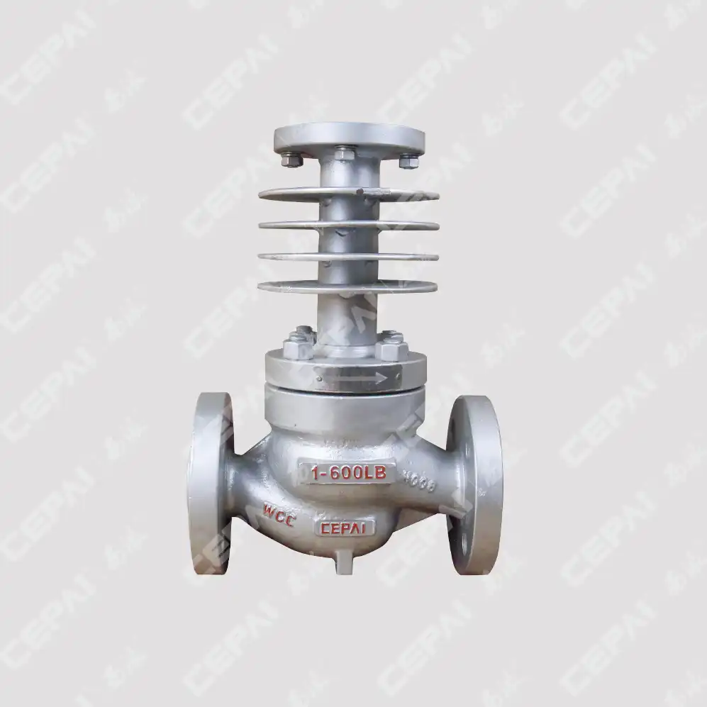
Upon receiving your Pneumatic Control Valve, conduct a thorough inspection before proceeding with installation. First, verify that the delivered valve matches the purchase specifications in terms of size, pressure class, materials, and connections. Carefully remove all shipping protective covers while noting the flow direction arrow marked on the valve body, as incorrect flow direction can severely impact performance or cause damage. Inspect the valve body and trim components for any signs of damage that might have occurred during transport, paying particular attention to seating surfaces, gaskets, and connection faces. For threaded connections, examine threads for damage or distortion. For flanged valves, inspect flange faces for scratches or irregularities that could prevent proper sealing. Test the valve's movement by manually operating the actuator (if possible) to ensure smooth, unimpeded travel throughout its entire stroke range without binding or excessive resistance. For Pneumatic Control Valves with positioners, verify that calibration seals are intact and that all accessories (such as solenoids, limit switches, or position transmitters) are securely mounted and undamaged. Check that air connections are clean and free from debris, and confirm that all mounting bolts and connections are properly tightened. Document any discrepancies or concerns, as installing a damaged valve can lead to immediate leakage, poor control performance, or premature failure. This comprehensive pre-installation inspection serves as quality assurance before the valve enters your critical process system.
Installation Process and Best Practices
Proper Valve Orientation and Positioning
Correct orientation of your Pneumatic Control Valve is fundamental to its performance and longevity. Always install the valve according to the manufacturer's specific recommendations, as valve designs vary significantly across different types and manufacturers. Most importantly, verify the flow direction by locating the arrow indicator on the valve body, ensuring process fluid will flow in the designated direction. This is particularly critical for unbalanced valve designs where reverse flow can damage internal components or cause unexpected operation. The valve should be installed in a horizontal pipeline with the actuator positioned vertically above the valve body whenever possible. This orientation prevents uneven wear on valve stems and packing, minimizes side loading on trim components, and allows for proper drainage of condensate from the actuator. When space constraints require alternative mounting positions, consult the manufacturer's documentation for acceptable orientations and any compensatory measures that may be necessary. Consider accessibility for routine maintenance when determining the valve's position – allow sufficient clearance for actuator removal, stem packing adjustment, and positioner calibration. For valves operating at high temperatures, ensure adequate space for thermal expansion of piping and components. Pneumatic Control Valves should be installed away from pipe elbows, reducers, or other flow disturbances that can create turbulence, which affects control accuracy and accelerates valve wear. Ideally, maintain straight pipe runs of at least 10 pipe diameters upstream and 5 diameters downstream of the valve. Proper positioning sets the foundation for optimal valve performance throughout its service life.
Pneumatic Connections and Air Supply Requirements
The pneumatic system that powers your control valve is as crucial as the valve itself, requiring careful attention during installation. Begin by ensuring your instrument air supply meets or exceeds the quality standards outlined in ISA-7.0.01 or ISO 8573-1, which typically specify clean, dry air free from oil contamination. The air supply pressure must fall within the manufacturer's specified range for your particular Pneumatic Control Valve model, generally between 3-7 bar (45-100 psi). Installing a dedicated filter-regulator unit upstream of the valve's pneumatic connections helps maintain consistent air quality and pressure, protecting sensitive components from damage. When connecting air supply lines, use appropriately sized tubing—typically 6mm or 1/4" for smaller valves and 10mm or 3/8" for larger actuators—ensuring that the tubing material is compatible with your environment and application. Tubing should be properly supported to prevent stress on connections and should follow a path that minimizes exposure to heat sources or potential physical damage. Make connections using compression or push-to-connect fittings appropriate for your operating pressure, and verify all connections are leak-free using soap solution or dedicated leak detection fluid. For Pneumatic Control Valves operating in critical applications, consider implementing redundant air supplies or installing volume boosters to improve response time for larger actuators. In areas subject to freezing temperatures, air dryers or methanol injection systems may be necessary to prevent condensation and subsequent freezing in pneumatic lines. Properly installed and maintained pneumatic systems ensure responsive, reliable operation of your control valves, preventing erratic behavior that can disrupt processes or compromise safety.
Electrical Connections for Positioners and Accessories
Modern Pneumatic Control Valves often incorporate electronic positioners, limit switches, and other intelligent accessories that require proper electrical connections for optimal functionality. Begin by reviewing area classification requirements to ensure all electrical components meet necessary hazardous location certifications (e.g., ATEX, IECEx, or Class/Division ratings). When making electrical connections, strictly adhere to the manufacturer's wiring diagrams and terminal designations to prevent damage to sensitive electronics. For analog positioners, typically verify the correct polarity for the 4-20mA control signal and ensure proper grounding according to manufacturer specifications. Digital positioners using HART, Foundation Fieldbus, or Profibus protocols require additional attention to communication parameters and network addressing. Install appropriate cable glands that maintain the required ingress protection rating (typically IP66 or higher for industrial environments) and properly seal all unused conduit entries to prevent moisture ingress. Cable routing should minimize exposure to electromagnetic interference by maintaining separation from high-voltage power cables and using shielded cable where specified. For installations in vibration-prone environments, secure all cables with appropriate strain relief to prevent connection fatigue. After completing connections, verify signal integrity using appropriate test equipment before commissioning. For Pneumatic Control Valves with diagnostic capabilities, confirm proper communication with your control system by performing a loopback test. When installing in corrosive environments, apply protective compounds to exposed terminals and connections according to manufacturer recommendations. Proper electrical installation not only ensures accurate valve positioning but also enables advanced diagnostics and predictive maintenance capabilities that maximize the return on investment in smart valve technology.
Commissioning and Maintenance Considerations
Leak Testing and Initial Operation
Before bringing your newly installed Pneumatic Control Valve into full service, comprehensive leak testing and careful initial operation are essential to verify integrity and performance. Begin with a thorough visual inspection of all connections, ensuring gaskets are properly seated and all bolting is uniformly tightened to specified torque values. For pneumatic systems, apply instrument air pressure gradually while checking all connections with leak detection solution. For process connections, follow a systematic pressure testing procedure in accordance with applicable codes such as ASME B31.3 or EN 12266, typically starting at 50% of test pressure and incrementally increasing while monitoring for leaks. Pay particular attention to valve stem packing, body-to-bonnet joints, and end connections, as these are common leak points. Once leak integrity is confirmed, perform stroke testing by cycling the Pneumatic Control Valve through its entire range of travel several times while observing for smooth, consistent movement. For valves with positioners, verify that actual valve position accurately corresponds with the control signal throughout the entire range, making calibration adjustments as necessary. Check that fail-safe operation functions correctly by interrupting the air supply or control signal and confirming the valve moves to its designated fail position (open or closed) within the specified time frame. During initial operation with process fluid, gradually introduce flow while monitoring downstream pressure and flow characteristics. Listen for abnormal noise such as cavitation or excessive fluid velocity, which may indicate improper sizing or installation issues. For Pneumatic Control Valves in critical service, consider implementing a fugitive emissions monitoring program using portable detection equipment to ensure ongoing environmental compliance. Documenting all commissioning parameters establishes baseline performance data that will prove invaluable for future diagnostic and maintenance activities.
Calibration and Signal Verification
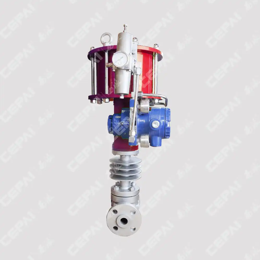
Precise calibration is essential for ensuring your Pneumatic Control Valve responds accurately to control signals and maintains process variables within desired parameters. Begin the calibration process by verifying the valve's bench set, which confirms the spring range and ensures the valve moves through its full stroke with the specified air pressure range. For valves equipped with positioners, follow the manufacturer's specific calibration procedure, which typically involves setting zero and span points, as well as dead band and response time parameters. Digital positioners often require setting additional parameters such as valve characterization curves to optimize control performance for your specific application. Verify calibration by performing a five-point check (0%, 25%, 50%, 75%, and 100% of input signal), documenting both the input signal and the resulting valve position at each point. For critical applications, expand this to an eleven-point check to verify linearity throughout the entire range. Measure hysteresis by approaching each test point from both increasing and decreasing signal directions, ensuring the difference remains within acceptable limits (typically less than 1%). For Pneumatic Control Valves in closed-loop control systems, perform step response testing to verify the valve can achieve the required positioning speed without excessive overshoot. When calibrating valves with smart positioners, utilize digital communication protocols to access additional diagnostic information and fine-tune parameters such as filtering, cutoff values, and travel limits. After completing calibration, document all settings and parameter values for future reference and maintenance activities. For optimal performance in varying process conditions, consider implementing adaptive or self-calibrating positioners that can automatically adjust to changing friction or process characteristics over time. Proper calibration not only ensures accurate process control but also minimizes unnecessary valve movement that can accelerate wear on trim components.
Preventive Maintenance Schedule and Troubleshooting
Implementing a structured preventive maintenance program is crucial for maximizing the service life and reliability of your Pneumatic Control Valves. Develop a comprehensive maintenance schedule based on the valve's criticality, operating conditions, and manufacturer recommendations. At minimum, quarterly visual inspections should be performed to check for external leakage, corrosion, or unusual noise during operation. Monthly checks of air supply quality using dewpoint measurement and particulate testing help prevent contamination-related failures. Stem packing should be inspected semi-annually for leakage and adjusted as necessary, though over-tightening must be avoided as it increases friction and accelerates wear. For Pneumatic Control Valves with smart positioners, leverage diagnostic capabilities by performing signature analysis annually to detect internal wear, increased friction, or developing issues before they lead to failure. Air filter elements should be replaced according to manufacturer schedules or more frequently in dusty environments. When troubleshooting performance issues, follow a systematic approach starting with verification of proper air supply pressure and quality, then checking for binding in valve movement, and finally examining electrical signal integrity. Common problems include hunting (continuous oscillation around setpoint), which may indicate oversized valves or excessive friction; incomplete stroking, often caused by inadequate actuator sizing or increased process forces; and slow response, typically resulting from restrictions in pneumatic lines or positioner issues. For valves that fail their performance criteria, implement a condition-based maintenance approach, prioritizing repairs based on operational impact and failure risk. Maintain detailed records of all maintenance activities, parts replacements, and performance tests to identify recurring issues and optimize future maintenance intervals. For critical Pneumatic Control Valves, consider implementing online monitoring systems that provide continuous condition assessment and early warning of developing problems, allowing maintenance to be scheduled during planned outages rather than emergency situations.
Conclusion
Proper installation of Pneumatic Control Valves is a critical investment in your system's reliability, efficiency, and safety. By following this comprehensive guide, you can ensure optimal valve performance while minimizing downtime and maintenance costs. CEPAI Group's exceptional durability, high-precision control performance, and extensive R&D achievements make our pneumatic control valves the preferred choice for demanding industrial applications worldwide. Our ISO-certified quality management system ensures zero-defect manufacturing, while our comprehensive pre-sales technical consultation and after-sales service guarantee your complete satisfaction. Ready to enhance your fluid control systems with industry-leading valve technology? Contact our expert team today at cepai@cepai.com to discuss your specific application requirements or schedule a personalized consultation.
References
1. Smith, J.R. & Johnson, A.T. (2023). Advanced Pneumatic Control Valve Installation Techniques for Industrial Applications. Journal of Fluid Control Engineering, 45(3), 218-235.
2. Williams, P.B. (2024). Best Practices for Pneumatic Valve Calibration and Maintenance. Industrial Process Control Handbook (5th ed.). McGraw-Hill Professional.
3. Chen, X.L. & López, M.R. (2023). Optimization of Pneumatic Control Valve Performance in High-Pressure Systems. International Journal of Valve Technology, 18(2), 87-103.
4. Thompson, B.K. (2024). Pneumatic Control Valve Selection and Installation: A Comprehensive Guide. American Society of Mechanical Engineers Press.
5. Patel, S.V. & Anderson, G.E. (2023). Troubleshooting Common Issues in Pneumatic Control Valve Systems. Handbook of Process Control Instrumentation (7th ed.). Wiley Industrial Press.
6. Nakamura, H. & Miller, D.S. (2024). Impact of Installation Practices on the Longevity of Industrial Control Valves. Journal of Engineering Asset Management, 12(4), 342-358.

Get professional pre-sales technical consultation and valve selection services, customized solution services.

About CEPAI
