How Do You Size a Liquid Turbine Flowmeter Correctly?
Liquid turbine flowmeters are appreciated for their rapid response, great repeatability, and extensive application in fuel, chemical, and water lines. But most unsatisfactory installations are due to sizing errors rather than instrument faults. If you go too big, the meter will not read well at low flow. If you go too small, the pressure drop will increase, the rotor will spin too quickly, and bearing life will be reduced. The correct solution is to match the meter to actual flow, fluid, and piping conditions – not merely to pipe diameter. This tutorial explains the scaling procedure clearly and step-by-step using straightforward language. The information comes from the CEPAI Group technical team, a high-tech maker of valves, instruments, and wellhead equipment.
Define the Duty Before You Pick a Size
Fluid Properties and Cleanliness
We begin with the liquid. It works best with clean, low-viscosity liquids like water, light oils, solvents, and various fuels where the rotor may spin freely, and the pulse signal is linear. Collect density, viscosity at operating temperature, vapor pressure, and any information on solids or fibers. Viscosity is especially important since the linear range of the meter is lowered for thicker fluid and the calibration may need to be adjusted to actual viscosity. Tell your supplier what fluid you are using, and the range of situations and the sizing will be accurate the first time.
Data to gather:
- Fluid name and composition
- Density and viscosity at normal, min, and max temperature
- Vapor pressure at operating temp
- Cleanliness: Solid, fiber, or contaminant detected
Flow Range and Turndown
Next comes the range of flow. For a liquid turbine flowmeter, precision and linearity are necessary throughout a range of flow, generally a turndown of around 10 to 1 from minimum to highest linear flow. Provide the start-up, cleaning, and peak flow rates for minimal, normal, and maximum conditions. The optimal flow should be in the upper two-thirds of the linear range of the meter where the rotor speed is stable, and the signal is strong. You don't want to be at the very bottom end of the spectrum since it will give you poor resolution and unnecessary uncertainty.
Operating Pressure and Temperature
Pressure and temperature determine body rating, bearing and rotor materials, and pickup design. A hot process line or high pressure transfer system with a liquid turbine flowmeter needs ratings above the highest expected values, including surges. For cryogenic and hot services, special attention to materials and clearances is necessary since thermal expansion has an effect on the performance of the rotor. Provide typical and maximum design conditions and cleaning or steam-out cycles so that your provider can confirm that the chosen meter will perform safely during its complete duty.
| Sizing Input | Why It Matters |
|---|---|
| Fluid and viscosity | Sets linear range and calibration |
| Min, normal, max flow | Determines meter size and turndown |
| Pressure and temperature | Determines body rating and materials |
| Cleanliness | Determines need for strainer or filter |
Match the Meter to the Flow, Not the Pipe
Sizing by Flow Rate and Velocity
One common mistake is to match the line length to the meter. The liquid turbine flowmeter should be selected from the flow range tables of the meter itself such that the expected flow falls well within its linear span. Use concentric reducers if the result is less than the pipe and transfer gradually. Velocity in the meter bore must be within the parameters established by the manufacturer; too high a velocity causes wear and noise. Sizing by flow keeps the meter in its sweet spot, and usually reduces expense from buying a size to suit the pipe.
Pressure Drop and Cavitation Margin
All turbine meters create a pressure drop, and that loss rises roughly with the square of flow. Compare the estimated loss at maximum flow with the pressure your system can stand to lose. The other half of the story is cavitation. If the pressure at the rotor is below the vapor pressure of the liquid, bubbles form and damage the blades and the measurement. A rule of thumb is that the downstream back pressure should be at least twice the meter pressure drop plus 1.25 times the vapor pressure. So keeping an eye on this margin on your liquid turbine flowmeter keeps the rotor safe and the reading honest.
K-Factor, Pulse Output, and Resolution
The K-factor is the key to signal scaling and tells you how many pulses the meter outputs per volume unit. A liquid turbine flowmeter creates a frequency that is proportional to flow. For example, the pulse rate at minimum flow must be high enough to be read cleanly by your controller or totalizer, yet the rate at maximum flow must be within the input constraints. Please provide the K-factor and calibration data. Make sure it is compatible with your flow computer or PLC. Good pulse resolution means more reproducible batching, mixing, and easier auditing of custody transfer.
| Sizing Check | Practical Rule |
|---|---|
| Normal flow position | Upper two-thirds of linear range |
| Turndown | About 10:1 for the linear range |
| Back pressure | At least 2 × pressure drop + 1.25 × vapor pressure |
| Pulse signal | Within the receiving instrument's frequency limits |
Build the Piping Around the Meter
Straight Runs and Flow Conditioning
Turbine rotors are vulnerable to swirl and altered velocity patterns. The normal recommendation for a liquid turbine flowmeter is a straight run of around 10 pipe diameters upstream and 5 downstream, with flow straighteners or conditioning plates if space is tight or disturbances are severe. The elbow, the partially opened valves, and the pumps at the input are the most prevalent sources of mistakes. Draw your piping plan early and verify available length, since moving the meter on paper is far cheaper than reconstructing the line once the pipe is welded.
Tips for layout:
- Keep valves downstream of the meter if feasible
- Avoid elbows and reducers directly upstream
- If the straight runs are short, use a flow conditioner.
- Install pressure and temperature points near the meter
Strainers, Filters, and Orientation
It's easier to shield than to replace the rotor. Install a strainer or filter upstream of the liquid turbine flowmeter with a mesh size as indicated by the manufacturer so that debris from construction or maintenance operations will not damage the blades or bearings. Always maintain the line filled with liquid; gas pockets and air entrainment upset the rotor and provide inaccurate results. Most meters may be used horizontally, and many can be installed vertically with the flow going up, but the orientation of calibration must be the same as the actual installation. Cheap air defense: venting and degassing stations
Signal, Display, and Integration
Think about how you will use the signal. A liquid turbine flowmeter may provide a local display, a flow computer or a PLC via pulse, frequency, or 4-20 mA outputs, and some models provide totalization, temperature adjustment, and communication protocols. Determine who needs the information and where, then determine cable type, distance, and grounding accordingly. Shielded cable, careful routing to avoid noise from motors and drives. Planning the integration at the sizing stage means no surprises at commissioning, and the control system gets the meter’s robust, linear signal unchanged.
| Installation Item | Recommended Practice |
|---|---|
| Upstream straight run | About 10 pipe diameters |
| Downstream straight run | About 5 pipe diameters |
| Protection | Strainer or filter ahead of the meter |
| Line condition | Full pipe, vented of air |
Verify, Certify, and Choose Your Partner
Calibration and Traceability
Size is tested using calibration. Each liquid turbine flowmeter should be given with a calibration certificate showing the K-factor, linearity, and repeatability, ideally on a fluid of viscosity close to that of your service fluid. Ask for traceability to national standards and periodic proving for custody transfer and regulated applications. Keep the certificate on record and arrange for re-verification at intervals suitable to the assignment. Good calibration data means operators can trust the findings and there’s a clear paper trail for auditors for every cubic meter recorded.
Hazardous Area and Safety Compliance
Fuel, solvent and chemical lines normally run through classified areas. Liquid turbine flowmeters with electronic pickups or transmitters must be appropriately certified for explosion protection in line with IEC 60079, for example ATEX, IECEx or equivalent. Inform your supplier of the area classification, gas group, and temperature class, as well as any pressure equipment requirements for your project. Matching certification to site protects people and equipment, eliminates delays during inspection, and confirms that the meter you size today will still be certified when it is deployed in the field.
Why CEPAI Is Ready to Help
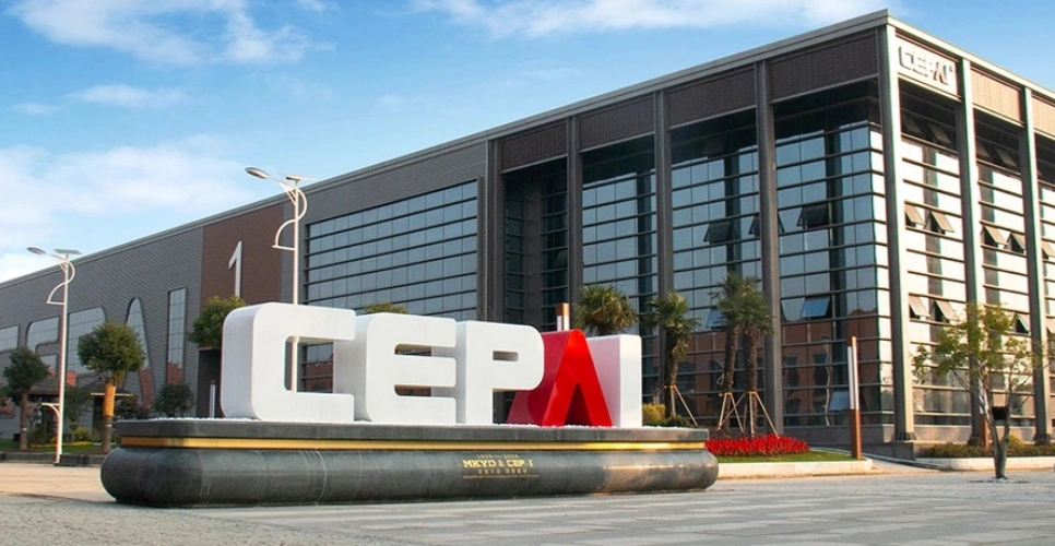
The best approach to get the most out of an instrument is to have a supplier that understands the whole process. Founded in 2009, CEPAI Group occupies an area of 56,000 square meters with a registered capital of 200 million yuan. It is a national high-tech enterprise involved in the development and manufacturing of wellhead equipment, pipeline and regulating valves, instruments, and meters. So engineers can count on a single partner for the selection and supply of products, as it has API Q1, API 6A, API 6D, API 16C, ISO 9001, ISO 14001, ISO 45001, ISO 3834, ISO 17025, CE, and PR2 certifications, operates a CNAS-recognized laboratory, and is a qualified supplier to major oil, gas, and chemical companies.
Conclusion
A proper sizing of a liquid turbine flowmeter begins with the process and works outward. Then you start with fluid properties, flow range, pressure, and temperature, and then choose the meter from its own flow table, not the pipe size. Verify pressure drop, cavitation margin, and pulse resolution, and make plumbing with enough straight runs, a strainer, and a fully vented line. Finish with calibration and area certification, and a supplier that can assist you post-delivery. Following these practices will result in accurate readings, longer rotor life, and fewer commissioning surprises. CEPAI Group combines proven quality methods, a validated laboratory, and deep industry experience to allow engineers to size, choose, and install flow instruments with confidence at every stage.
FAQ
1. What fluids suit a liquid turbine flowmeter?
Clean, low-viscosity liquids such as water, light oils, solvents, and fuels.
2. What turndown can I expect?
Typically about 10 to 1 across the linear flow range.
3. How much straight pipe is needed?
Roughly 10 diameters upstream and 5 downstream, or a flow conditioner.
4. Why is a strainer recommended?
It protects the rotor and bearings from debris.
5. How do I avoid cavitation?
Keep back pressure at or above twice the pressure drop plus 1.25 times the vapor pressure.
Need Help Sizing a Liquid Turbine Flowmeter? Contact CEPAI
A correct size begins with accurate data. Send your fluid properties, minimum, normal, and maximum flow, pressure, temperature, and piping layout to sales@cepai.com, and the CEPAI team will reply with sizing advice, a datasheet, and a tailored quotation. With certified quality systems, a CNAS-recognized laboratory and wide experience across oil, gas, chemical and power projects, we are ready to help you measure liquid turbine flowmeter accurately and reliably.

Get professional pre-sales technical consultation and valve selection services, customized solution services.
About CEPAI
Popular Blogs