A Checklist for Maintaining Your High-Temperature Control Valve
Industrial facilities operating under extreme thermal conditions face a critical challenge that can cost millions in unexpected downtime and emergency repairs. When your High-Temperature Control Valve fails during peak production, the consequences extend far beyond immediate operational disruptions. The domino effect includes compromised product quality, safety hazards, regulatory compliance issues, and substantial financial losses that could have been prevented through proper maintenance protocols. This comprehensive maintenance checklist provides essential guidance for protecting your High-Temperature Control Valve investment, ensuring optimal performance, extending operational lifespan, and maintaining the reliability your critical processes depend on for continuous, safe, and efficient operation.
Understanding High-Temperature Control Valve Operation Fundamentals
-
Critical Components and Thermal Stress Management
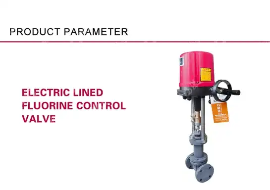
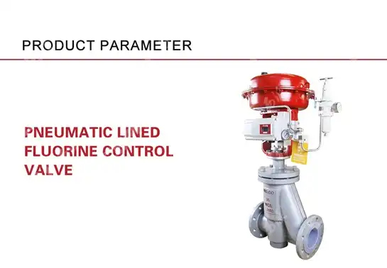
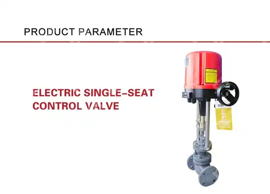
High-Temperature Control Valve systems operate under extreme conditions that place significant stress on every component within the assembly. The valve body, manufactured from specialized materials like WCB, CF8, or CF8M, must withstand continuous thermal cycling that can range from -60°C to over 600°C in industrial applications. These temperature fluctuations create expansion and contraction cycles that affect dimensional stability, sealing integrity, and overall valve performance. The internal components, including 304, 316, and 316L stainless steel elements, respond differently to thermal stress, requiring careful monitoring and maintenance protocols to prevent premature failure. Understanding these thermal dynamics is essential for developing effective maintenance strategies that address the unique challenges of High-Temperature Control Valve operation in demanding industrial environments. The pressure balance spool design in modern High-Temperature Control Valve systems provides superior performance under thermal stress by minimizing the effects of inlet pressure variations on valve positioning accuracy. This sophisticated mechanism requires precise calibration and regular inspection to maintain optimal function throughout temperature extremes. The electric actuator, operating at 220V or 380V with 4-20mADC control signals, must compensate for thermal expansion effects on valve stem positioning while maintaining accurate flow control. Regular calibration verification ensures that the control characteristics, whether equal percentage or linear, remain consistent across the operating temperature range, preventing process instabilities that could compromise product quality or safety.
-
Thermal Expansion Considerations and Material Selection
The selection of appropriate materials for High-Temperature Control Valve construction directly impacts maintenance requirements and operational reliability. Advanced alloys and specialized coatings applied to internal surfaces provide enhanced resistance to thermal shock, corrosion, and erosion that commonly occur in high-temperature applications. The extended valve cover design, rated for -40°C to -196°C applications, incorporates thermal barriers and insulation systems that protect sensitive components from extreme temperature exposure. These protective measures require regular inspection and maintenance to ensure continued effectiveness throughout the valve's operational life. Flexible graphite and PTFE packing materials used in High-Temperature Control Valve assemblies provide superior sealing performance under thermal cycling conditions. However, these materials require periodic replacement based on operating conditions, thermal exposure duration, and process fluid characteristics. The bolt pressing gland design allows for field adjustment and replacement without complete valve removal, reducing maintenance downtime and associated costs. Understanding the thermal limits and degradation patterns of these sealing materials enables predictive maintenance scheduling that prevents unexpected failures and extends valve service life.
Pre-Operational Inspection Protocols for High-Temperature Control Valves
-
Visual Assessment and Documentation Requirements
Comprehensive pre-operational inspection begins with detailed visual assessment of all external High-Temperature Control Valve components, focusing on signs of thermal damage, corrosion, or mechanical wear that could indicate developing problems. The flange connections, rated for PN16, 40, or 64 pressures, require careful examination for proper bolt torque, gasket condition, and surface flatness that ensures reliable sealing under thermal cycling conditions. Any signs of previous leakage, indicated by staining or corrosion around joint surfaces, must be thoroughly investigated and remediated before returning the valve to service. Documentation of inspection findings provides valuable trending data for optimizing maintenance intervals and predicting component replacement requirements. The electric actuator housing and electrical connections require special attention during pre-operational inspection, as thermal cycling can cause connection loosening and insulation degradation. All control signal connections, whether 4-20mADC current or 0-10V voltage signals, must be verified for proper continuity and signal integrity throughout the expected operating temperature range. The ambient temperature rating of -30°C to +70°C for the actuator requires verification that installation conditions remain within these limits to prevent premature failure. Position feedback systems and limit switches require functional testing to ensure accurate valve position indication throughout the full stroke range.
-
Pressure Testing and Leak Detection Procedures
Systematic pressure testing protocols for High-Temperature Control Valve systems must address both ambient and elevated temperature conditions to verify sealing integrity under actual operating conditions. The ANSI B16.104 Level IV compliance for metal valve seats and Class VI compliance for non-metallic seats establishes specific leakage criteria that must be verified during maintenance activities. Hydrostatic testing at 1.5 times the rated working pressure provides initial verification of structural integrity, while pneumatic testing with appropriate safety precautions allows for leak detection under controlled conditions. These tests must be conducted using proper safety protocols and certified pressure testing equipment to ensure accurate results and personnel safety. Advanced leak detection methods, including ultrasonic testing and thermal imaging, provide enhanced capability for identifying developing seal problems before they become critical failures. The straight cage type ball valve design used in many High-Temperature Control Valve applications requires specialized testing procedures that address the unique sealing mechanisms and flow characteristics of this configuration. Bubble testing with approved leak detection solutions provides visual confirmation of seal integrity at all pressure boundaries, while electronic leak detectors offer quantitative measurement capabilities for precise leakage assessment. All testing results must be documented and compared against manufacturer specifications and industry standards to ensure compliance with safety and performance requirements.
Routine Maintenance Tasks and Inspection Schedules
-
Daily and Weekly Monitoring Activities
Effective High-Temperature Control Valve maintenance programs incorporate daily visual inspections and weekly operational parameter monitoring to identify developing problems before they impact system performance. Daily inspections focus on external indicators of valve condition, including actuator position indication, control signal response, and evidence of process fluid leakage around packing and flange connections. The DN15-400mm nominal diameter range of High-Temperature Control Valve installations requires inspection procedures scaled to valve size and criticality within the process system. Operators should monitor for unusual sounds, vibrations, or temperature variations that could indicate internal component wear or malfunction. Weekly monitoring activities include verification of control signal accuracy, position feedback calibration, and response time measurements that ensure continued compliance with process control requirements. The 4-20mADC control signal range requires periodic verification using calibrated test equipment to confirm signal integrity and actuator response throughout the full operating range. Temperature measurements at multiple points on the valve body provide trending data for thermal performance analysis and early detection of process condition changes that could affect valve operation. These routine measurements should be recorded in maintenance logs for trending analysis and predictive maintenance planning.
-
Monthly and Quarterly Comprehensive Assessments
Monthly comprehensive assessments of High-Temperature Control Valve systems include detailed inspection of all accessible components, calibration verification of control and feedback systems, and performance testing under actual operating conditions. The equal percentage or linear flow characteristics must be verified through flow measurement or calculated based on pressure drop and position data to ensure continued accuracy of process control. Packing adjustment may be required monthly, depending on operating conditions and thermal cycling frequency, to maintain proper sealing while avoiding excessive stem friction that could affect actuator performance. Quarterly assessments provide opportunities for more extensive testing and component replacement based on predictive maintenance indicators. The opening range of 0-90 degrees or 0-180 degrees, depending on valve configuration, requires verification through full stroke testing with position feedback monitoring to identify any restrictions or binding conditions. Internal inspection, when possible without complete disassembly, allows assessment of trim condition, seat wear, and internal corrosion or erosion that could affect performance or safety. These assessments should include review of maintenance records, trending analysis of key parameters, and planning for major maintenance activities or component replacements.
Critical Component Maintenance and Replacement Guidelines
-
Actuator Service and Calibration Procedures
The electric actuator system represents the most complex component in High-Temperature Control Valve assemblies, requiring specialized maintenance procedures and calibration equipment for optimal performance. Regular inspection of motor windings, gear train lubrication, and position feedback mechanisms ensures reliable operation throughout the demanding thermal conditions typical of high-temperature applications. The voltage requirements of 220V or 380V, with frequency specifications of 50Hz or 60Hz, must be verified periodically to ensure proper power supply characteristics that prevent motor damage or performance degradation. Control signal calibration requires precision instruments capable of generating and measuring 4-20mADC signals with accuracy sufficient to maintain process control specifications. Actuator calibration procedures must address both ambient and elevated temperature conditions to ensure accurate position control throughout the operating temperature range. The control range should match the valve's flow characteristics, whether equal percentage or linear, to provide optimal process control performance. Position feedback systems require calibration verification at multiple points throughout the stroke range, with particular attention to end positions where mechanical stops or limit switches provide travel limitation. Any observed drift in calibration or response time should be investigated and corrected promptly to prevent process control problems or safety issues.
-
Internal Component Inspection and Replacement
Internal component inspection of High-Temperature Control Valve systems requires careful planning and appropriate safety procedures due to the potential for retained heat and process fluid contamination. The pressure balance spool design allows for trim replacement without complete valve body removal in many cases, reducing maintenance time and system downtime. However, inspection of internal surfaces, seat condition, and flow path erosion requires complete disassembly using proper tools and procedures to prevent component damage. All internal components should be examined for signs of thermal damage, corrosion, erosion, or mechanical wear that could affect performance or safety. Replacement of internal components must use materials and specifications identical to original equipment to maintain design performance characteristics and safety certifications. The 304, 316, and 316L stainless steel internal materials require proper handling and storage to prevent contamination or damage that could compromise corrosion resistance or mechanical properties. Seat replacement requires precision machining and fitting procedures to ensure proper sealing characteristics and flow coefficients. All replacement components should be verified against manufacturer specifications and quality certifications before installation to ensure compatibility and performance.
Troubleshooting Common High-Temperature Control Valve Issues
-
Performance Degradation and Flow Irregularities
Performance degradation in High-Temperature Control Valve systems typically manifests as reduced flow capacity, irregular control response, or inability to maintain precise flow regulation under varying process conditions. These symptoms often result from internal component wear, seat damage, or actuator calibration drift that develops gradually over extended operation periods. Systematic troubleshooting begins with verification of control signals, position feedback accuracy, and comparison of actual flow performance against original design specifications. The straight cage type ball valve design provides inherent resistance to erosion and cavitation damage, but extreme operating conditions can still cause performance degradation over time. Flow irregularities may indicate internal obstruction, partial seat damage, or actuator binding that prevents smooth valve operation throughout the stroke range. Pressure drop measurements across the valve at various positions provide quantitative assessment of flow capacity and can identify internal restrictions or damage. Temperature distribution measurements on the valve body can reveal internal flow patterns and identify areas of concern such as thermal shock damage or localized erosion. These diagnostic techniques help isolate the root cause of performance problems and guide appropriate corrective actions.

-
Actuator and Control System Malfunctions
Actuator and control system malfunctions in High-Temperature Control Valve applications often result from thermal effects on electrical components, control signal interference, or mechanical binding due to thermal expansion. The ambient temperature rating of -30°C to +70°C for actuator components establishes operational limits that must be maintained through proper installation and thermal protection measures. Control signal problems, whether 4-20mADC current or 0-10V voltage variations, require systematic troubleshooting using appropriate test equipment to isolate signal source, transmission, or actuator response issues. Power supply verification ensures that voltage and frequency specifications remain within acceptable ranges for reliable motor operation. Mechanical binding or excessive operating torque often develops gradually as thermal cycling causes component wear or misalignment within the actuator assembly. Position feedback systems may drift due to thermal effects on sensors or mechanical linkages, requiring recalibration or component replacement to restore accuracy. Emergency shutdown capability and fail-safe positioning must be verified periodically to ensure proper safety system function in the event of power loss or control system failure. These troubleshooting procedures require systematic approach and proper documentation to identify recurring problems and optimize maintenance procedures.
Safety Protocols and Regulatory Compliance Standards
-
Lockout/Tagout Procedures for High-Temperature Systems
Safety protocols for High-Temperature Control Valve maintenance must address the unique hazards associated with elevated temperature operation, retained heat in valve components, and potential exposure to hazardous process fluids. Lockout/tagout procedures require complete isolation of the valve from process pressure, electrical power, and control signals before beginning any maintenance activities. The extended valve cover design used in low-temperature applications requires additional safety considerations for personnel protection from extremely cold surfaces and potential cryogenic fluid exposure. All maintenance personnel must be trained in proper safety procedures and equipped with appropriate personal protective equipment for the specific hazards present. The ANSI150, 300, and 600 pressure ratings typical of High-Temperature Control Valve installations require specific safety procedures for pressure isolation and verification before maintenance activities begin. Residual pressure bleeding and thermal conditioning of valve components may be required before safe access can be achieved. Emergency response procedures must address potential exposure to high-temperature process fluids, electrical hazards from actuator power systems, and environmental release of hazardous materials. These safety protocols must be documented, regularly reviewed, and practiced to ensure effective implementation during actual maintenance activities.
-
Quality Assurance and Documentation Requirements
Quality assurance programs for High-Temperature Control Valve maintenance must ensure compliance with applicable safety codes, environmental regulations, and performance standards throughout the service life of the equipment. The API Q1, API 6A, API 6D, API 16C, and API 602 certifications require specific documentation and quality control procedures for maintenance activities that could affect safety or performance characteristics. ISO 9001 quality management systems provide framework for consistent maintenance practices, documentation control, and continuous improvement of maintenance procedures based on field experience and performance data. Maintenance documentation must include detailed records of all inspection findings, test results, component replacements, and calibration activities to support regulatory compliance and warranty requirements. The CNAS nationally recognized laboratory certification ensures that testing and calibration activities meet international standards for accuracy and traceability. CE certification requirements may apply to maintenance activities that modify or significantly alter valve configuration or performance characteristics. All documentation must be maintained in accordance with regulatory requirements and company policies to support equipment history tracking and maintenance optimization activities.
Conclusion
Effective maintenance of High-Temperature Control Valve systems requires comprehensive understanding of thermal effects, systematic inspection procedures, and adherence to safety protocols that protect personnel and equipment while ensuring reliable operation. The combination of routine monitoring, predictive maintenance techniques, and proactive component replacement based on condition assessment provides optimal balance between operational reliability and maintenance costs. Success depends on proper training, quality documentation, and commitment to continuous improvement of maintenance practices based on field experience and advancing technology.
Cooperate with CEPAI Group Co., LTD.
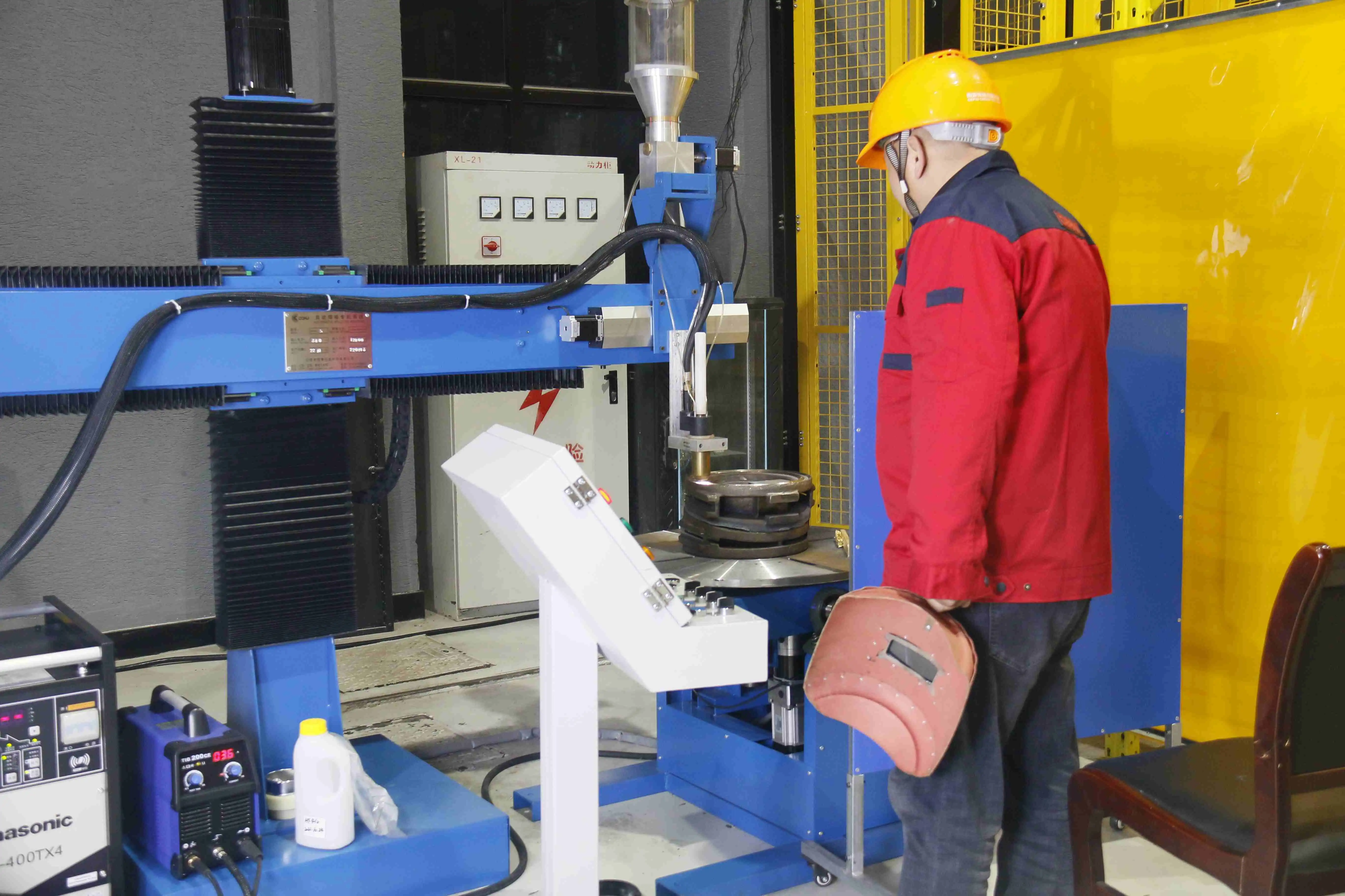
CEPAI Group Co., LTD., established in 2009 with registered capital of 200 million yuan, stands as a leading China High-Temperature Control Valve manufacturer and China High-Temperature Control Valve factory offering comprehensive solutions for demanding industrial applications. Our 56,000 square meter facility houses advanced manufacturing capabilities and nationally recognized testing laboratories that ensure High Quality High-Temperature Control Valve production meeting international standards. As a certified China High-Temperature Control Valve supplier, we provide competitive High-Temperature Control Valve price options and China High-Temperature Control Valve wholesale services to customers worldwide. Our extensive product range includes High-Temperature Control Valve for sale alongside pneumatic and electric actuated valves designed for extreme operating conditions. With API certifications and ISO quality systems, we deliver exceptional value and reliability. Contact cepai@cepai.com for your High-Temperature Control Valve requirements.
FAQ
Q: How often should High-Temperature Control Valve packing be replaced?
A: Packing replacement frequency depends on operating temperature, thermal cycling, and process conditions, typically every 6-12 months for high-temperature applications.
Q: What are the signs of internal seat damage in High-Temperature Control Valves?
A: Key indicators include reduced flow capacity, irregular control response, increased leakage past the seat, and inability to achieve tight shutoff.
Q: How do I calibrate the position feedback system on electric actuators?
A: Use certified test equipment to verify 4-20mADC signals at multiple stroke positions, adjusting feedback potentiometers to match actual valve position.
Q: What safety precautions are required when maintaining High-Temperature Control Valves?
A: Essential precautions include proper lockout/tagout procedures, thermal protection, pressure isolation verification, and appropriate personal protective equipment for temperature exposure.
References
1. "Control Valve Handbook: Fourth Edition" - Fisher Controls International LLC, comprehensive guide covering valve selection, sizing, and maintenance procedures for industrial applications.
2. "High Temperature Valve Design and Application Guidelines" - American Petroleum Institute, technical publication addressing materials selection and maintenance requirements for extreme temperature service.
3. "Industrial Valve Maintenance and Repair Standards" - Valve Manufacturers Association, industry standard covering best practices for valve maintenance, testing, and documentation requirements.
4. "Process Control Instrumentation Technology: Eighth Edition" - Curtis D. Johnson, detailed coverage of control valve operation, calibration, and troubleshooting procedures for industrial process applications.
_1745994738000.webp)
Get professional pre-sales technical consultation and valve selection services, customized solution services.

About CEPAI
