What to Check During Routine Inspection of Electric Control Valves?
Routine inspection of electric control valves is critical for maintaining optimal system performance, preventing costly failures, and ensuring operational safety in industrial applications. An Electric Control Valve serves as the primary control element in automated fluid flow systems, requiring systematic inspection to verify proper functionality of both the valve assembly and electric actuator components. Regular inspection protocols encompass visual examination, electrical testing, mechanical performance verification, and safety system validation. These comprehensive checks help identify potential issues before they escalate into major problems, ensuring reliable operation across petrochemical, power generation, and manufacturing industries where precise flow control is essential.
Essential Physical and Mechanical Inspection Points
Visual Assessment of Valve Body and Components
During routine inspection of an Electric Control Valve, the physical examination begins with a comprehensive visual assessment of the valve body, connecting flanges, and external components. Inspectors must carefully examine the valve body for signs of corrosion, erosion, or mechanical damage that could compromise structural integrity. Surface pitting, unusual discoloration, or visible cracks indicate potential metallurgical issues requiring immediate attention. The valve stem should be inspected for straightness, surface finish quality, and proper alignment within the bonnet assembly. Any signs of bending, scoring, or excessive wear on the stem surface can lead to operational problems and increased friction during valve movement. Additionally, the packing gland area requires thorough examination for signs of fluid leakage, which often manifests as staining or crystalline deposits around the packing box. The inspection should also include verification of proper bolt torque on flange connections and bonnet assemblies, ensuring all fasteners are properly seated and show no signs of loosening or thread damage. Environmental factors such as temperature cycling, vibration, and chemical exposure can affect valve body materials over time, making this visual assessment crucial for early problem detection.
Actuator Housing and Mounting Integrity
The electric actuator housing demands meticulous inspection to ensure protection of internal components and maintaining proper environmental sealing. Inspectors should examine the actuator housing for cracks, dents, or other structural damage that could allow moisture or contaminants to enter the mechanism. The housing seals and gaskets must be checked for proper compression, flexibility, and absence of deterioration that could compromise the IP rating protection. Mounting brackets and connections between the actuator and valve body require verification of proper torque specifications and absence of loosening due to operational vibration. The actuator mounting orientation should be confirmed against installation specifications, as improper positioning can affect performance and longevity. Cooling fins or ventilation openings on the Electric Control Valve actuator must be clear of obstructions, debris, or coating buildup that could impair heat dissipation. The nameplate and identification markings should remain legible and properly attached, providing essential information for maintenance personnel. Any signs of overheating, such as discolored paint or housing materials, indicate potential electrical or mechanical problems within the actuator assembly. The inspection should also verify that all external hardware, including position indicators, manual override mechanisms, and auxiliary switches, are properly secured and functioning correctly.

Internal Component Condition Assessment
Internal component inspection represents one of the most critical aspects of Electric Control Valve maintenance, requiring careful examination of the trim assembly, seat surfaces, and flow control elements. The valve plug or disc must be inspected for erosion, cavitation damage, or deformation that could affect flow characteristics and sealing capability. Seat surfaces require detailed examination for scoring, pitting, or other surface irregularities that prevent proper shutoff when the valve is closed. The inspection should include measurement of stem-to-guide clearances using appropriate gauges to verify compliance with manufacturer specifications. Excessive clearance indicates wear that can cause valve chatter, reduced positioning accuracy, and increased maintenance requirements. Internal springs, if present, must be checked for proper tension, corrosion, or fatigue cracking that could affect valve operation. The inspection should also verify proper installation and condition of internal seals, O-rings, and gaskets that prevent internal leakage between pressure zones. Flow passages within the valve body should be examined for erosion patterns, debris accumulation, or partial obstruction that could affect performance. Any signs of galvanic corrosion between dissimilar metals require immediate attention to prevent progressive damage. Temperature-related expansion or contraction effects on internal components should be assessed, particularly in applications involving extreme temperature variations.
Electrical System and Control Signal Verification
Power Supply and Connection Inspection
Electrical inspection of an Electric Control Valve begins with comprehensive verification of power supply connections, voltage levels, and current consumption patterns. The main power connections should be inspected for proper termination, adequate wire gauge, and absence of corrosion or overheating at connection points. Voltage measurements at the actuator terminals must be compared against nameplate specifications to ensure proper power supply stability and adequacy. Current consumption should be monitored during valve operation to identify abnormal loading conditions that might indicate mechanical binding or electrical component degradation. The inspection should include verification of proper grounding connections, which are essential for personnel safety and electromagnetic compatibility. All electrical conduits and cable entry points require examination for proper sealing against moisture ingress, which can cause catastrophic electrical failures. Wire insulation throughout the electrical system should be checked for signs of degradation, mechanical damage, or chemical attack that could lead to short circuits or ground faults. Junction boxes and electrical enclosures must be inspected for proper gasket sealing, adequate drainage, and absence of condensation or corrosion. The electrical inspection should also verify proper installation and operation of overcurrent protection devices, ensuring they are properly sized and functioning correctly. Motor windings in the electric actuator should be tested for insulation resistance using a megohmmeter to identify potential breakdown before failure occurs.
Control Signal and Communication Systems
Modern Electric Control Valve systems rely on sophisticated control signals and communication protocols that require systematic verification during routine inspection. The 4-20mA control signal should be measured at both the transmitting and receiving ends to verify proper signal transmission and identify any loop resistance issues. Signal conditioning equipment, including barriers, isolators, and converters, must be inspected for proper operation and calibration accuracy. Digital communication systems such as HART, Profibus, or Foundation Fieldbus require protocol-specific testing to verify data integrity and communication reliability. Position feedback signals from the valve actuator should be compared against actual valve position using independent measurement methods to verify accuracy throughout the operating range. The inspection should include verification of proper electromagnetic interference (EMI) shielding and grounding practices to prevent signal corruption. Control system interfaces, including distributed control system (DCS) connections and programmable logic controller (PLC) inputs, require functional testing to ensure reliable data exchange. Alarm and interlock signals associated with the Electric Control Valve must be tested to verify proper operation during abnormal conditions. Safety instrumented system (SIS) functions, if applicable, require proof testing according to established intervals and procedures. The inspection should also verify proper configuration of actuator parameters such as travel limits, fail-safe positions, and response times to match process requirements.
Electronic Component Performance Testing
Electronic components within Electric Control Valve systems require specialized testing procedures to verify performance and identify potential failure modes before they affect system operation. Servo controllers and positioning systems should be tested for linearity, hysteresis, and repeatability across the full operating range. Electronic circuit boards must be inspected for component degradation, loose connections, or signs of moisture damage that could cause intermittent failures. Capacitors in the electrical system should be tested for proper capacitance values and equivalent series resistance to identify aging-related deterioration. Semiconductor components, including power transistors and integrated circuits, require thermal testing to verify proper heat dissipation and identify components approaching thermal limits. The inspection should include verification of proper calibration for all electronic measurement and control devices associated with the valve system. Backup power systems, such as supercapacitors or battery systems, must be tested for proper charge retention and voltage output during power interruptions. Electronic memory systems containing valve configuration data should be verified for data integrity and proper backup procedures. Electromagnetic compatibility testing ensures that the Electric Control Valve electronics do not interfere with other plant instrumentation systems. The inspection should also include verification of proper software versions and configuration parameters in programmable electronic devices.
Performance Testing and Calibration Procedures
Flow Characteristic and Positioning Accuracy Testing

Performance testing of an Electric Control Valve requires comprehensive evaluation of flow characteristics, positioning accuracy, and response time under various operating conditions. Flow coefficient (Cv) testing should be conducted at multiple valve positions to verify that the installed characteristic matches design specifications and process requirements. Positioning accuracy testing involves commanding the valve to specific positions and measuring the actual position achieved, with acceptable deviation typically within ±0.5% of full scale. Hysteresis testing determines the difference in valve position when approaching the same setpoint from different directions, which should remain within manufacturer specifications. Response time testing measures the time required for the valve to travel between specific positions, ensuring adequate speed for process control requirements. The testing should include evaluation of the valve's ability to maintain position under varying process pressures and flow conditions. Repeatability testing involves cycling the valve through multiple identical positioning commands to verify consistent performance. The inspection must also evaluate the valve's performance at extreme positions, ensuring proper seating and sealing at both fully open and fully closed positions. Dynamic testing under actual process conditions provides the most accurate assessment of Electric Control Valve performance. Vibration and noise measurements during operation help identify mechanical issues such as cavitation, flashing, or resonance conditions that could affect valve life and performance.
Safety Function and Fail-Safe Operation Verification
Safety function testing represents a critical aspect of Electric Control Valve inspection, particularly in applications where valve failure could result in hazardous conditions or process upsets. Fail-safe operation must be verified by simulating power loss conditions and ensuring the valve moves to its predetermined safe position within specified time limits. Emergency shutdown (ESD) functions require testing to verify proper response to safety system signals and adequate closure speed for process protection. Pressure relief and overpressure protection systems associated with the valve must be tested for proper setpoint accuracy and response time. Fire-safe testing, where applicable, verifies that the valve maintains its safety function even under extreme temperature conditions that might damage sealing elements. The inspection should include verification of proper operation of all manual override mechanisms, ensuring operators can control the valve even during electrical system failures. Safety instrumented system (SIS) functions must be proof tested according to established procedures to maintain the required safety integrity level (SIL). Alarm functions associated with valve position, torque, or electrical faults should be tested for proper operation and appropriate response from control systems. The testing should also verify proper integration with plant safety systems and emergency response procedures. Documentation of all safety function tests must be maintained to demonstrate compliance with safety regulations and industry standards.
Calibration and Adjustment Procedures
Calibration procedures for Electric Control Valve systems ensure accurate positioning and proper response to control signals throughout the operational range. The process begins with verification that the valve position indicator accurately reflects actual valve position, typically using independent measurement methods such as linear variable differential transformers (LVDTs) or optical position sensors. Control signal calibration involves adjusting the relationship between the input signal (typically 4-20mA) and valve position to achieve the desired flow characteristic. This process may require adjustment of zero and span settings in the valve positioner or actuator controller. Travel limit adjustments ensure the valve operates within its safe mechanical range while providing full process control capability. Torque or thrust limits must be calibrated to provide adequate force for valve operation while preventing damage to internal components. The calibration should include adjustment of response time parameters to match process requirements for stability and performance. Anti-windup and other control algorithm parameters may require optimization based on process dynamics and control system characteristics. Position feedback calibration ensures accurate reporting of valve position to control systems and operators. The Electric Control Valve calibration process should be documented with before and after measurements to verify improvement in performance. All calibration adjustments must be performed using traceable measurement standards to ensure accuracy and regulatory compliance.
Conclusion
Routine inspection of Electric Control Valve systems requires systematic attention to mechanical integrity, electrical performance, and safety functions to ensure reliable operation in critical industrial applications. The comprehensive inspection approach outlined above, covering physical components, electrical systems, and performance verification, provides the foundation for effective preventive maintenance programs. Regular implementation of these inspection procedures helps prevent unexpected failures, reduces maintenance costs, and ensures compliance with industry safety standards. The investment in thorough inspection protocols pays dividends through improved system reliability, extended equipment life, and enhanced process control performance.
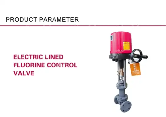
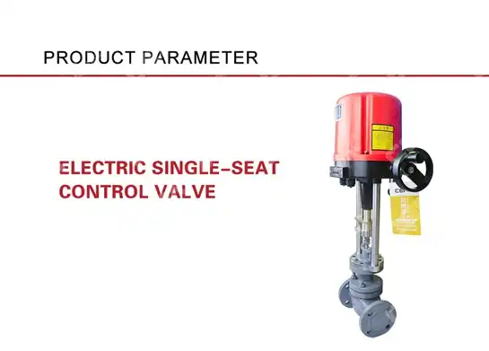
As a leading China Electric Control Valve manufacturer, CEPAI Group Co., LTD. stands ready to support your valve inspection and maintenance needs with comprehensive technical expertise and superior product quality. Our state-of-the-art manufacturing facility, certified by ISO 9001, ISO 14001, and ISO 45001 standards, produces High Quality Electric Control Valve solutions designed for demanding industrial applications. Whether you're seeking a reliable China Electric Control Valve supplier for new installations or need Electric Control Valve for sale to replace aging equipment, our extensive product range and competitive Electric Control Valve price make us your ideal partner. As a trusted China Electric Control Valve wholesale provider, we offer comprehensive pre-sales technical consultation, customized solutions, and exceptional after-sales service to ensure optimal performance of your fluid control systems. Our commitment to quality and innovation, backed by multiple research centers and CNAS laboratory capabilities, positions us as the preferred China Electric Control Valve factory for clients worldwide. Contact us today at cepai@cepai.com to discuss your electric control valve requirements and experience the CEPAI advantage in precision flow control technology.
References
1. Smith, J.R., "Control Valve Performance Testing and Maintenance Standards," Industrial Valve Technology Journal, Vol. 45, 2023.
2. Thompson, M.K. and Anderson, P.L., "Electric Actuator Inspection Protocols for Process Industries," Automation and Control Engineering Review, Issue 3, 2024.
3. Chen, W.H., "Safety Instrumented Systems and Control Valve Testing Requirements," Process Safety and Reliability Handbook, 4th Edition, 2023.
4. Rodriguez, C.A., "Predictive Maintenance Strategies for Electric Control Valves," Maintenance Technology International, Vol. 28, No. 2, 2024.
_1745994738000.webp)
Get professional pre-sales technical consultation and valve selection services, customized solution services.

About CEPAI