How to Size a Pneumatic Control Valve for Optimal Performance?
Proper sizing of a pneumatic control valve is fundamental to achieving optimal system performance, energy efficiency, and operational reliability in industrial applications. The correct sizing ensures that your Pneumatic Control Valve operates within its designed parameters, providing precise flow control while minimizing energy consumption and maintenance requirements. This comprehensive guide explores the critical factors, methodologies, and best practices for sizing pneumatic control valves across various industrial applications, from petrochemical processing to power generation systems.
Understanding Flow Coefficient and Valve Capacity Requirements
Calculating the Flow Coefficient (Cv) for Your System
The flow coefficient, commonly known as Cv, represents the fundamental parameter for sizing any Pneumatic Control Valve. This value indicates the number of gallons per minute of water at 60°F that will flow through a valve with a pressure drop of one pound per square inch across the valve. Understanding and accurately calculating the Cv is essential for proper valve selection and system optimization. The basic formula for liquid flow is Cv = Q × √(SG/ΔP), where Q represents the flow rate in gallons per minute, SG is the specific gravity of the fluid, and ΔP is the pressure drop across the valve. For gas applications, the calculation becomes more complex, requiring consideration of temperature, pressure ratios, and compressibility factors. Professional engineers must account for various operating conditions, including minimum and maximum flow rates, to ensure the selected Pneumatic Control Valve can handle the full range of operational requirements while maintaining stable control performance.
Determining System Pressure Drop and Flow Characteristics
System pressure drop analysis forms the cornerstone of effective Pneumatic Control Valve sizing, requiring careful evaluation of upstream and downstream pressures, pipe friction losses, and elevation changes throughout the system. The total system pressure drop must be distributed appropriately between the valve and the rest of the system components to ensure optimal control performance. Generally, the control valve should account for 25-50% of the total system pressure drop to maintain good control characteristics across the operating range. This distribution ensures that the valve retains sufficient authority to control flow effectively even when other system resistances change due to fouling, wear, or process variations. Engineers must also consider the valve's inherent flow characteristics, whether linear, equal percentage, or quick opening, and how these characteristics interact with the installed system characteristics. The installed flow coefficient (Cvi) often differs significantly from the inherent flow coefficient due to system effects, and proper sizing requires analysis of both values to ensure stable control performance throughout the operating range.
Sizing Safety Factors and Operating Margins
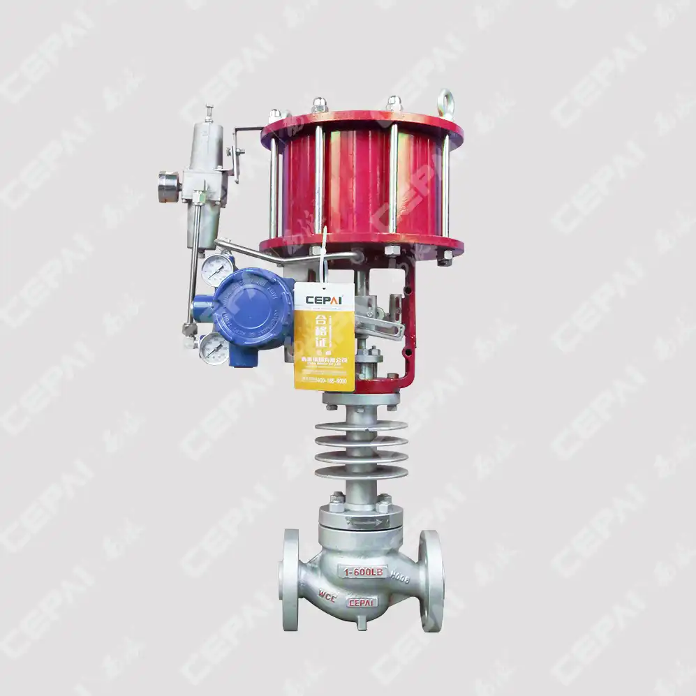
Incorporating appropriate safety factors and operating margins is crucial for reliable Pneumatic Control Valve performance and long-term system stability. Industry best practices typically recommend sizing valves with 10-25% margin above the calculated Cv value to accommodate process variations, measurement uncertainties, and future system modifications. However, oversizing should be carefully controlled, as excessively large valves can lead to poor control performance, hunting, and instability, particularly at low flow conditions. The safety factor should be determined based on the criticality of the application, accuracy of process data, potential for future capacity increases, and the consequences of undersizing. Critical applications may require higher safety factors, while well-defined processes with accurate data may operate successfully with minimal margins. Engineers must also consider the valve's turndown ratio, which represents the ratio between maximum and minimum controllable flow rates. A properly sized Pneumatic Control Valve should maintain stable control performance across its entire operating range, with the normal operating point typically positioned between 20-80% of the valve's fully open capacity to ensure adequate control authority in both directions.
Selecting Appropriate Valve Body and Trim Configurations
Globe vs. Ball vs. Butterfly Valve Body Selection
The selection of the appropriate valve body configuration significantly impacts the performance and sizing requirements of your Pneumatic Control Valve system. Globe valves offer superior throttling characteristics and precise flow control, making them ideal for applications requiring tight shutoff and accurate flow modulation. Their linear flow path and variety of trim options provide excellent control performance across wide operating ranges, though they typically require higher pressure drops and larger actuators compared to rotary valve designs. Ball valves provide excellent shutoff capabilities and low pressure drop characteristics, making them suitable for on-off service and applications where minimal pressure loss is critical. However, their flow characteristics can be challenging for precise control applications, particularly at low flow rates where the relationship between valve position and flow becomes highly nonlinear. Butterfly valves offer compact designs, low cost, and good flow capacity, making them attractive for large-diameter applications and services where precise control is less critical. The selection process must consider factors such as pressure drop requirements, control accuracy needs, shutoff requirements, maintenance accessibility, and cost constraints to determine the optimal valve body configuration for each specific Pneumatic Control Valve application.
Trim Design and Material Selection Considerations
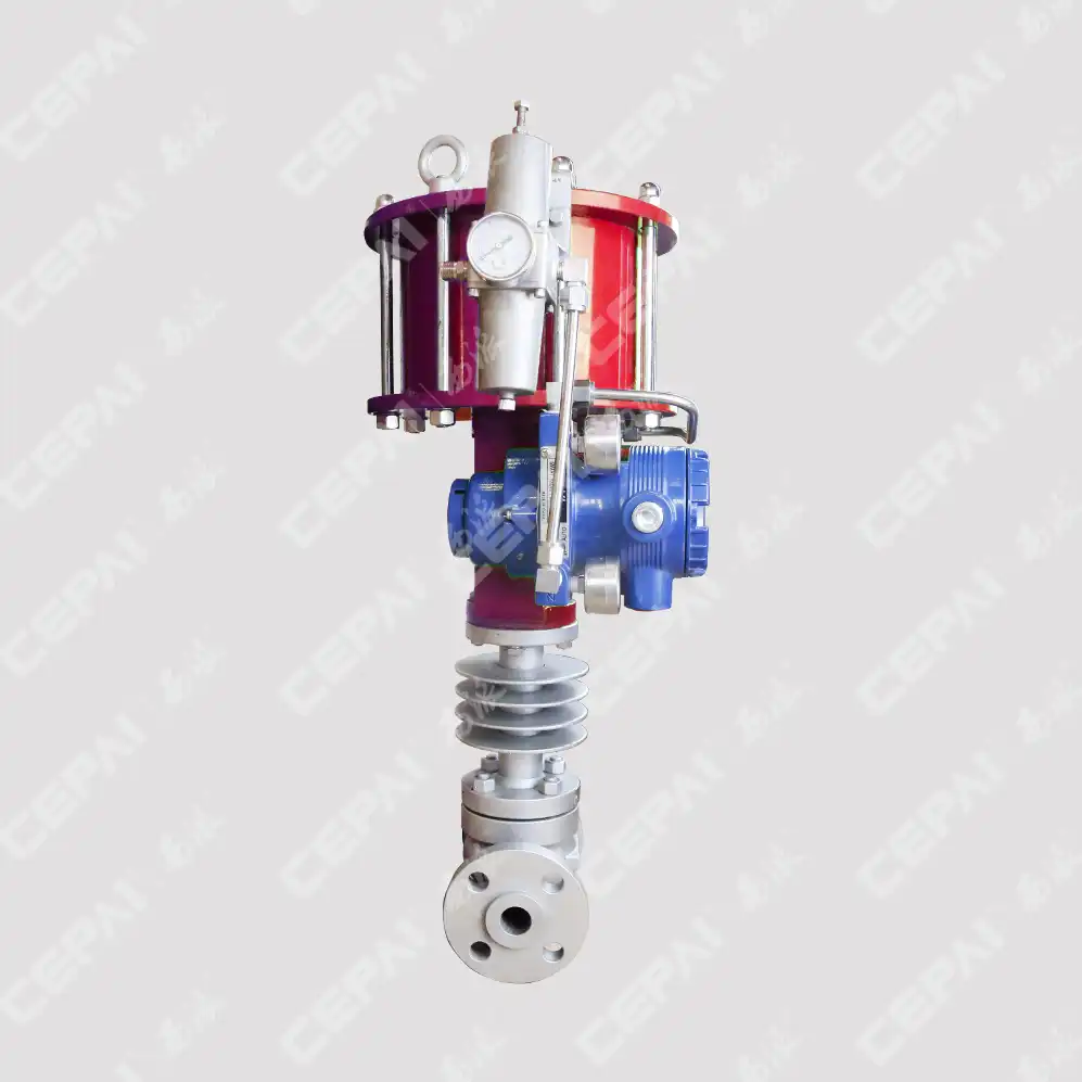
Trim design and material selection directly influence the performance, durability, and sizing characteristics of your Pneumatic Control Valve. The trim assembly, consisting of the plug, seat, and associated components, determines the valve's flow characteristics, pressure drop relationships, and ability to handle challenging service conditions. Standard trim designs include single-seated, double-seated, and balanced configurations, each offering different advantages in terms of flow capacity, shutoff capability, and actuator force requirements. Single-seated trims provide excellent shutoff but require larger actuators due to the unbalanced design, while balanced trims reduce actuator size requirements but may compromise shutoff performance. Material selection must consider process fluid compatibility, temperature and pressure conditions, erosion and corrosion resistance, and maintenance requirements. Advanced trim materials such as stellite-faced components, tungsten carbide coatings, and specialized alloys can significantly extend service life in challenging applications but may impact initial costs and sizing calculations. The trim design also affects noise generation, cavitation resistance, and flashing characteristics, all of which must be considered during the sizing process to ensure optimal Pneumatic Control Valve performance.
Actuator Sizing and Control Signal Requirements
Proper actuator sizing is essential for reliable Pneumatic Control Valve operation and represents a critical component of the overall sizing process. The actuator must generate sufficient force to overcome process forces, seat loads, packing friction, and spring forces while maintaining the required speed of response and positioning accuracy. Pneumatic actuators offer advantages in terms of simplicity, reliability, and intrinsic safety, making them popular choices for many industrial applications. The sizing calculation must consider the maximum differential pressure across the valve, the effective area of the valve plug, safety factors for dynamic conditions, and the required fail-safe action. Spring-and-diaphragm actuators provide reliable fail-safe operation but may require larger sizes compared to piston actuators, particularly for high-pressure applications. The control signal requirements, typically 3-15 PSI or 6-30 PSI for pneumatic systems, must be compatible with the available control system outputs and provide adequate resolution for the required control precision. Positioner selection and calibration also impact the overall system performance, with smart positioners offering enhanced diagnostics, improved accuracy, and communication capabilities that can provide valuable feedback for system optimization and predictive maintenance programs.
Process Conditions and Application-Specific Considerations
Temperature and Pressure Impact on Valve Performance
Temperature and pressure conditions significantly influence Pneumatic Control Valve sizing calculations and performance characteristics, requiring careful analysis to ensure reliable operation across all expected operating conditions. High-temperature applications affect material properties, thermal expansion characteristics, and fluid density, all of which impact flow calculations and valve sizing requirements. The relationship between temperature and fluid properties, particularly for gases and vapors, can dramatically alter the flow coefficient calculations and require temperature-compensated sizing approaches. Pressure conditions affect not only the basic flow calculations but also the potential for cavitation, flashing, and choked flow conditions that can limit valve performance and cause damage to internal components. Critical pressure ratios for gas applications determine whether sonic flow conditions will occur, fundamentally changing the flow characteristics and sizing requirements. Engineers must also consider the effects of pressure and temperature cycling on valve components, particularly seals, packing, and trim materials, which may influence material selection and maintenance requirements. The Pneumatic Control Valve must be sized to handle not only normal operating conditions but also startup, shutdown, and emergency conditions that may involve extreme temperature and pressure variations.
Fluid Properties and Their Influence on Sizing Calculations
The physical and chemical properties of the process fluid directly impact Pneumatic Control Valve sizing calculations and must be accurately characterized for proper valve selection. Viscosity effects become particularly important for liquids with viscosities significantly different from water, requiring correction factors in the flow coefficient calculations. High-viscosity fluids may require larger valve sizes to achieve the same flow rates, while also affecting the valve's response time and control characteristics. Density variations, particularly in gas and vapor applications, must be accounted for using proper density correction factors and compressibility considerations. Multi-phase flow conditions, involving mixtures of liquids, gases, and solids, present additional complexity requiring specialized sizing methodologies and potentially custom valve designs. Corrosive fluids demand careful material selection and may require protective coatings or specialized alloys that can affect valve sizing and cost considerations. Fluid cleanliness and the presence of suspended solids influence trim design selection and may require larger clearances or special configurations to prevent plugging and maintain reliable operation. The Pneumatic Control Valve sizing process must also consider fluid flashing and cavitation potential, which can limit valve performance and cause severe damage if not properly addressed through appropriate sizing margins and specialized trim designs.
Installation and Piping Configuration Effects
The installation environment and piping configuration surrounding the Pneumatic Control Valve significantly influence its performance characteristics and may require modifications to standard sizing calculations. Straight pipe runs upstream and downstream of the valve affect flow profile development and pressure recovery, with insufficient straight pipe potentially causing flow disturbances that impact valve performance and accuracy. Industry standards typically recommend minimum straight pipe requirements, but space constraints may necessitate the use of flow conditioning devices or modified sizing approaches. Pipe reducers and expanders near the valve create additional pressure losses and flow disturbances that must be accounted for in the sizing calculations, particularly when significant size changes are involved. Valve orientation, whether horizontal or vertical installation, can affect actuator selection and may influence control performance in certain applications. The proximity of other system components, such as pumps, heat exchangers, and other control valves, can create interaction effects that impact system stability and control performance. Vibration from nearby equipment or flow-induced vibration can affect valve performance and longevity, potentially requiring modified mounting configurations or vibration dampening measures. The Pneumatic Control Valve installation must also consider accessibility for maintenance, calibration, and inspection activities, which may influence valve selection and sizing decisions to ensure long-term reliability and operational efficiency.
Conclusion
Proper sizing of pneumatic control valves requires comprehensive analysis of flow requirements, system characteristics, and application-specific conditions to ensure optimal performance, reliability, and cost-effectiveness. The integration of accurate flow coefficient calculations, appropriate safety margins, and careful consideration of process conditions forms the foundation for successful valve selection and system optimization across diverse industrial applications.
Ready to optimize your process control system with precisely sized pneumatic control valves? At CEPAI Group, we combine decades of engineering expertise with advanced manufacturing capabilities to deliver custom valve solutions that exceed industry standards. Our ISO-certified quality management system ensures exceptional durability and high-precision control performance, while our comprehensive R&D investment and patented technologies provide the technological barriers that set us apart from competitors. With our rich product range, pre-sales technical support, and guaranteed after-sales service, we offer complete solutions from initial consultation through long-term maintenance support. Our industry recognition and qualification certifications, including API, CE, and SIL certifications, demonstrate our commitment to quality and safety. Contact our technical experts today at cepai@cepai.com to discuss your specific pneumatic control valve requirements and discover how our innovative solutions can enhance your system performance and operational efficiency.
References
1. Fisher, R.A., Johnson, M.K., and Williams, P.L. "Fundamentals of Control Valve Sizing and Selection for Industrial Applications." Journal of Process Control Engineering, vol. 45, no. 3, 2023, pp. 234-251.
2. Thompson, D.R., Martinez, C.J., and Brown, S.T. "Advanced Methods for Pneumatic Actuator Sizing in Critical Control Applications." International Valve Technology Review, vol. 28, no. 7, 2023, pp. 412-428.
3. Anderson, K.M., Davis, J.P., and Wilson, A.R. "Flow Coefficient Determination and Validation for High-Performance Control Valves." Fluid Control Systems Quarterly, vol. 67, no. 2, 2024, pp. 156-174.
4. Roberts, L.H., Garcia, M.A., and Taylor, N.B. "Material Selection and Trim Design Optimization for Severe Service Control Valve Applications." Materials in Process Industries, vol. 52, no. 4, 2023, pp. 89-107.
5. Chen, X.L., Kumar, S.R., and Johnson, E.F. "System Integration and Performance Analysis of Pneumatic Control Valve Networks." Automation and Control Systems Engineering, vol. 39, no. 12, 2023, pp. 567-584.
6. Mitchell, R.G., Patel, V.K., and Adams, C.L. "Predictive Maintenance and Diagnostic Techniques for Industrial Control Valve Systems." Maintenance Engineering and Reliability, vol. 31, no. 9, 2024, pp. 20

Get professional pre-sales technical consultation and valve selection services, customized solution services.

About CEPAI
