How to Read Valve Specification Sheets: A Beginner’s Guide for Purchasers?
Understanding valve specification sheets is crucial for making informed purchasing decisions in industrial applications. These technical documents contain essential information about valve performance, compatibility, and operational parameters that directly impact system efficiency and safety. For purchasers dealing with complex systems involving Pneumatic Control Valves, mastering the interpretation of specification sheets ensures optimal equipment selection, reduces operational risks, and maximizes return on investment while maintaining compliance with industry standards and regulations.
Understanding Basic Valve Specifications and Technical Parameters
Pressure Ratings and Temperature Limits
Pressure ratings represent one of the most critical specifications when evaluating valve suitability for industrial applications. These ratings indicate the maximum pressure a valve can safely handle under specific temperature conditions, typically expressed in PSI, bar, or MPa. For Pneumatic Control Valve applications, understanding pressure classifications such as ANSI Class 150, 300, 600, 900, 1500, and 2500 is essential. Each class corresponds to specific pressure limits at various temperatures, with higher class numbers indicating greater pressure handling capabilities. Temperature limits work in conjunction with pressure ratings, as valve materials and sealing components experience different stress levels at elevated temperatures. The relationship between pressure and temperature follows established curves, where increased temperature generally reduces maximum allowable pressure. Purchasers must carefully examine both maximum and minimum operating temperatures, considering factors such as thermal expansion, material properties, and potential thermal cycling effects that could impact valve performance over time.
Flow Coefficients and Sizing Parameters
Flow coefficient (Cv) represents the volumetric flow rate of water at 60°F that passes through a valve with a one PSI pressure drop across the valve. This fundamental parameter enables accurate valve sizing for specific applications and ensures optimal system performance. For Pneumatic Control Valve selection, understanding Cv values helps determine the valve's flow capacity and its ability to handle required flow rates while maintaining acceptable pressure losses. Flow characteristics describe how the flow rate changes relative to valve opening position, typically categorized as linear, equal percentage, or quick opening characteristics. Linear flow provides proportional flow increase with valve opening, making it suitable for applications requiring precise flow control. Equal percentage characteristics offer better control at low flow rates, where small changes in valve position produce proportional changes in flow rate. Quick opening characteristics provide maximum flow with minimal valve travel, ideal for on-off applications. Rangeability, another crucial parameter, indicates the ratio between maximum and minimum controllable flow rates, with higher rangeability values offering better control precision across wider operating ranges.
Material Specifications and Compatibility
Material selection significantly impacts valve performance, longevity, and compatibility with process media. Specification sheets detail body materials, trim materials, seal materials, and coating options, each serving specific functions and offering different advantages. Common body materials include carbon steel, stainless steel grades (304, 316, 316L), duplex stainless steel, and exotic alloys for specialized applications. Trim materials, including valve seats, discs, and stems, require careful consideration based on process conditions, wear resistance requirements, and chemical compatibility. For Pneumatic Control Valve applications, material compatibility with process fluids prevents corrosion, erosion, and contamination issues that could compromise system integrity. Hardness ratings, such as Rockwell or Brinell scales, indicate material resistance to wear and deformation under operational stresses. Chemical compatibility charts help purchasers verify material suitability for specific process media, considering factors such as pH levels, chloride content, and potential for stress corrosion cracking. Environmental factors, including atmospheric conditions, temperature cycling, and exposure to corrosive elements, also influence material selection decisions for optimal valve performance and service life.
Decoding Performance Characteristics and Operating Conditions
Actuator Specifications and Control Methods
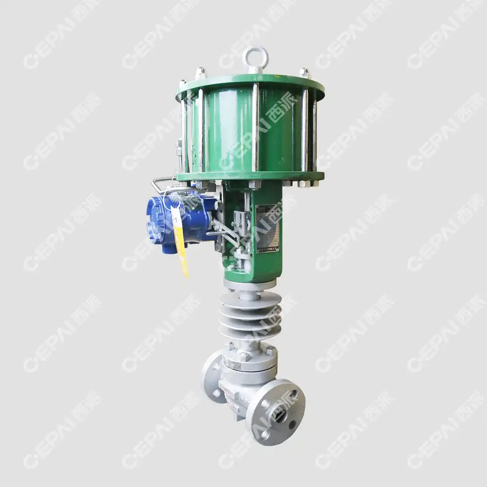
Actuator specifications define how valves respond to control signals and provide the mechanical force necessary for valve operation. Pneumatic actuators, commonly used with Pneumatic Control Valve systems, require specific air pressure ranges, typically 3-15 PSI or 4-20 mA control signals for precise positioning. Spring return actuators provide fail-safe operation by automatically returning valves to predetermined positions during power or signal loss, critical for safety-sensitive applications. Double-acting actuators offer greater force output and positioning accuracy but require continuous air supply for operation. Actuator sizing involves calculating required torque or thrust forces based on valve size, pressure differential, and packing friction, ensuring adequate force margins for reliable operation under all operating conditions. Response time specifications indicate how quickly valves can move between positions, affecting system dynamic response and control loop stability. Positioner specifications detail feedback mechanisms that ensure accurate valve positioning relative to control signals, compensating for hysteresis, friction, and other mechanical variations that could affect control accuracy.
Leakage Classifications and Sealing Performance
Leakage classifications provide standardized methods for evaluating valve sealing performance under various conditions. ANSI/FCI 70-2 and IEC 60534-4 standards define leakage classes ranging from Class I through Class VI, with Class VI representing the tightest shutoff capabilities. For Pneumatic Control Valve applications requiring precise flow control, understanding leakage specifications helps ensure compliance with environmental regulations and process requirements. Seat leakage testing involves measuring actual leakage rates under specified pressure differentials and comparing results against established standards. Packing leakage specifications address stem sealing performance, particularly important for environmental compliance and safety considerations. Fugitive emissions requirements, governed by standards such as API 641 and ISO 15848, specify maximum allowable leakage rates for volatile organic compounds and hazardous materials. Emergency shutdown capabilities require specific leakage performance levels to ensure effective process isolation during emergency conditions. Understanding these classifications enables purchasers to select valves with appropriate sealing performance for their specific applications while meeting regulatory requirements and operational objectives.
Environmental and Installation Requirements
Environmental specifications encompass operating conditions that affect valve performance and longevity in real-world applications. Ambient temperature ranges define acceptable installation environments, considering both extreme cold conditions that could affect material properties and high-temperature environments that might require special cooling or insulation measures. Humidity specifications address corrosion protection requirements and electrical component performance in moisture-rich environments. For Pneumatic Control Valve installations, understanding environmental specifications ensures proper valve selection for outdoor, indoor, hazardous area, or marine applications. Vibration resistance specifications indicate valve ability to maintain performance and structural integrity in high-vibration environments such as compressor stations or marine platforms. Seismic qualifications may be required for installations in earthquake-prone regions or critical infrastructure applications. Installation orientation requirements specify acceptable mounting positions and any limitations on valve orientation that could affect performance or maintenance access. Maintenance access requirements detail space requirements for routine maintenance, actuator removal, and component replacement, ensuring long-term serviceability in confined installation spaces.
Interpreting Safety Standards and Compliance Requirements
Industry Standards and Certifications
Industry standards provide frameworks for valve design, testing, and performance verification, ensuring consistency and reliability across different manufacturers and applications. API (American Petroleum Institute) standards, including API 6D for pipeline valves and API 598 for valve testing, establish requirements for valve design, materials, and testing procedures in oil and gas applications. ASME (American Society of Mechanical Engineers) standards, particularly ASME B16.34 for valve pressure-temperature ratings and ASME B16.5 for flange dimensions, provide essential design criteria for pressure vessel applications. For Pneumatic Control Valve applications, ISA (International Society of Automation) standards such as ISA-75.05 for control valve terminology and ISA-75.25 for control valve test procedures establish performance criteria and testing methods. European standards, including EN 12266 for valve testing and EN 1092 for flange specifications, may be required for equipment destined for European markets. Understanding these standards helps purchasers verify that valves meet applicable requirements and ensure compatibility with existing system components and regulatory requirements.
Safety Integrity Level (SIL) Requirements
Safety Integrity Level (SIL) ratings quantify the reliability of safety instrumented systems and their components, including safety-critical valves. SIL ratings range from SIL 1 (lowest) to SIL 4 (highest), with each level representing specific probability of failure on demand (PFD) ranges. For Pneumatic Control Valve applications in safety-critical services, SIL ratings ensure that valves provide adequate reliability for emergency shutdown, pressure relief, or process isolation functions. SIL 2 and SIL 3 ratings are most commonly specified for industrial applications, requiring extensive testing and documentation to verify failure rate performance. Proof test intervals, typically ranging from one to ten years, specify how frequently valves must be tested to maintain SIL rating validity. Common cause failure analysis examines potential failure modes that could affect multiple components simultaneously, requiring design measures to minimize such risks. Beta factors quantify the fraction of failures that could affect multiple components, with lower values indicating better common cause failure resistance. Understanding SIL requirements helps purchasers select appropriate valves for safety-critical applications while ensuring compliance with functional safety standards such as IEC 61508 and IEC 61511.
Fire Safety and Explosion Protection
Fire safety specifications address valve performance during fire exposure scenarios, ensuring continued operation or safe failure modes during emergency conditions. API 607 and API 6FA standards define fire testing procedures that simulate actual fire conditions, measuring valve performance after exposure to specified temperature profiles and time durations. Fire-safe valve designs incorporate features such as graphite secondary seals, metal-to-metal seating surfaces, and robust body construction to maintain sealing integrity during and after fire exposure. For Pneumatic Control Valve applications in flammable service, fire safety certifications ensure that valves will not contribute to fire propagation or loss of containment during emergency situations. Explosion protection requirements, governed by standards such as ATEX (European) and IECEx (International), specify design criteria for equipment used in potentially explosive atmospheres. Explosion-proof enclosures, intrinsically safe designs, and increased safety constructions represent different approaches to explosion protection, each suitable for specific hazardous area classifications. Temperature classification codes (T1 through T6) specify maximum surface temperatures that equipment can reach without igniting surrounding explosive atmospheres. Understanding these requirements ensures proper valve selection for hazardous area installations while maintaining operational safety and regulatory compliance.
Conclusion
Mastering valve specification interpretation empowers purchasers to make informed decisions that optimize system performance, ensure safety compliance, and minimize long-term operational costs. By understanding technical parameters, performance characteristics, and safety requirements, purchasers can confidently select valves that meet specific application needs while avoiding costly mistakes and potential safety hazards that could compromise system integrity.
Ready to source premium pneumatic control valves for your industrial applications? CEPAI Group stands as your trusted China Pneumatic Control Valve factory and China Pneumatic Control Valve supplier, offering comprehensive solutions backed by advanced manufacturing capabilities and rigorous quality standards. As a leading China Pneumatic Control Valve manufacturer, we provide competitive China Pneumatic Control Valve wholesale pricing on our extensive product range. Whether you're seeking standard models or customized solutions, our Pneumatic Control Valve for sale inventory meets diverse industrial requirements at competitive Pneumatic Control Valve price points. Request your detailed Pneumatic Control Valve brochure today and discover why industry leaders choose CEPAI Group for their critical flow control applications. Contact our technical experts at cepai@cepai.com for personalized consultation and specification assistance.
References
1. Smith, J.A., & Johnson, M.R. (2019). Industrial Valve Technology: Design, Selection and Application. McGraw-Hill Professional Engineering. pp. 145-167.
2. Thompson, R.L., Davis, P.K., & Williams, S.C. (2020). "Control Valve Specification and Selection Criteria for Process Industries." Journal of Process Control Engineering, 42(3), 78-92.
3. Anderson, K.M., & Brown, T.E. (2018). Pneumatic Control Systems: Theory and Practice. 4th Edition. Butterworth-Heinemann Technical Publications. pp. 234-251.
4. Miller, D.F., Rodriguez, A.L., & Chen, H.W. (2021). "Safety Integrity Level Requirements for Industrial Valve Applications." International Journal of Safety Engineering, 15(2), 156-171.
_1745994738000.webp)
Get professional pre-sales technical consultation and valve selection services, customized solution services.

About CEPAI
