How to Calculate Cv in Pneumatic and Electric Valves?
Understanding the flow coefficient (Cv) calculation in pneumatic and electric valves is fundamental for engineers and technicians working in industrial automation and process control systems. The Cv value represents a valve's flow capacity under standardized conditions, serving as a critical parameter for proper valve sizing and selection. This comprehensive guide explores the methodologies, formulas, and practical considerations for calculating Cv in different Control Valve configurations, ensuring optimal system performance and efficiency in various industrial applications.
Understanding Cv Fundamentals and Standard Calculation Methods
Basic Cv Definition and Its Significance in Valve Selection
The flow coefficient Cv is defined as the number of gallons per minute of water at 60°F that will flow through a valve with a pressure drop of 1 psi across the valve. This standardized measurement allows engineers to compare different Control Valve options and select the most appropriate valve for specific applications. The Cv value is intrinsically linked to the valve's internal geometry, including the port size, trim design, and flow path configuration. For pneumatic and electric actuated valves, the Cv calculation becomes more complex due to the variable opening characteristics and the relationship between actuator position and flow area. Modern Control Valve designs incorporate sophisticated trim geometries that provide linear or equal percentage flow characteristics, directly impacting the Cv calculation methodology. Understanding these fundamentals is essential for proper valve sizing, as an incorrectly sized valve can lead to system instability, energy waste, or inadequate process control. The relationship between Cv and valve performance extends beyond simple flow calculations to encompass considerations of cavitation, noise generation, and long-term reliability in industrial applications.

Mathematical Formulas for Liquid Flow Applications
For liquid applications, the basic Cv calculation formula is Cv = Q × √(SG/ΔP), where Q represents the flow rate in gallons per minute, SG is the specific gravity of the liquid, and ΔP is the pressure drop across the valve in psi. This fundamental equation forms the basis for all liquid flow calculations in Control Valve sizing. However, real-world applications require modifications to account for factors such as viscosity corrections, temperature effects, and choked flow conditions. When dealing with viscous liquids, the Reynolds number must be calculated to determine if viscosity corrections are necessary. The formula becomes more complex when considering non-Newtonian fluids or liquids operating near their vapor pressure. For electric Control Valve systems, additional considerations include the response time of the actuator and the precision of positioning, which can affect the effective Cv at partial opening positions. The accuracy of Cv calculations directly impacts system performance, energy consumption, and operational costs. Modern digital Control Valve positioners incorporate algorithms that compensate for these variables, providing more accurate flow control throughout the valve's operating range.
Gas and Steam Flow Cv Calculations
Gas and steam applications require different calculation approaches due to the compressible nature of these fluids. For gas flow, the Cv calculation incorporates factors such as inlet pressure, temperature, molecular weight, and the compressibility factor Z. The basic formula becomes Cv = Q × √((SG × T × Z)/(520 × ΔP × P1)), where Q is the flow rate in standard cubic feet per hour, T is the absolute temperature, and P1 is the inlet pressure. For steam applications, the calculation must account for the specific properties of steam at different pressure and temperature conditions. Control Valve manufacturers provide steam tables and correction factors to ensure accurate sizing for these critical applications. The phenomenon of choked flow becomes particularly important in gas and steam applications, where the downstream pressure ratio affects the maximum achievable flow rate. Electric and pneumatic Control Valve actuators must be properly sized to handle the dynamic forces associated with high-pressure gas and steam applications. The accuracy of these calculations becomes even more critical in power generation, petrochemical, and process industries where steam and gas flow control directly impacts efficiency and safety. Advanced Control Valve designs incorporate features such as noise reduction trim and anti-cavitation technology to optimize performance in these challenging applications.
Pneumatic vs Electric Valve Cv Characteristics
Pneumatic Valve Actuator Impact on Flow Coefficient
Pneumatic actuators significantly influence the effective Cv characteristics of Control Valve systems through their inherent operational characteristics and response dynamics. The relationship between air pressure and actuator position creates unique flow characteristics that must be considered in Cv calculations. Unlike manual valves with fixed opening positions, pneumatic Control Valve systems exhibit variable Cv values that change with actuator stroke and air pressure variations. The spring-diaphragm configuration in pneumatic actuators creates a non-linear relationship between control signal and valve position, particularly noticeable in applications requiring precise flow control. This non-linearity affects the installed Cv characteristics, making it essential to consider the complete system response when calculating flow coefficients. Pneumatic actuators also introduce hysteresis effects, where the valve position may differ slightly between increasing and decreasing control signals, impacting the effective Cv calculation. The air supply pressure stability directly affects the actuator's ability to maintain consistent positioning, which in turn influences the valve's flow characteristics. Temperature variations in the pneumatic supply can cause actuator drift, affecting the relationship between commanded position and actual Cv. Modern pneumatic Control Valve systems incorporate positioners that provide feedback control to minimize these effects and maintain more consistent Cv characteristics throughout the operating range.
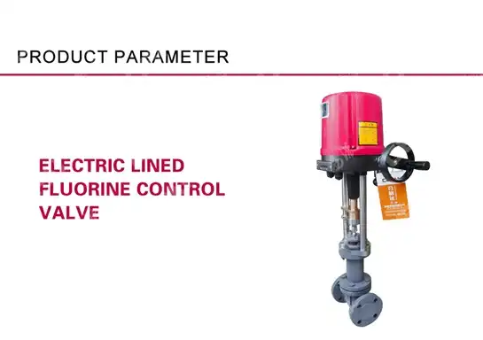
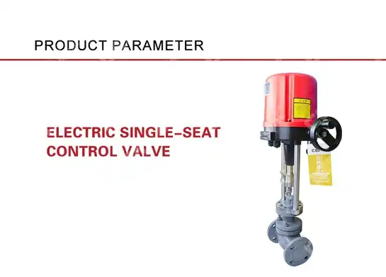
Electric Actuator Precision and Its Effect on Cv Accuracy
Electric actuators offer superior precision and repeatability compared to pneumatic systems, directly impacting the accuracy of Cv calculations and installed performance. The precise positioning capability of electric Control Valve actuators allows for more accurate correlation between commanded position and actual flow coefficient. Electric actuators eliminate the variable compliance issues associated with pneumatic systems, providing consistent force output regardless of ambient temperature or supply pressure variations. This precision enables more accurate Cv calculations, particularly in applications requiring fine flow control or operation at partial valve openings. The digital feedback systems integrated into modern electric Control Valve actuators provide real-time position information, allowing for dynamic Cv correction based on actual valve position. Electric actuators also offer programmable flow characteristics, enabling engineers to modify the relationship between control signal and valve position to achieve specific Cv curves. The absence of air consumption and the precise control capabilities make electric actuators particularly suitable for applications where accurate Cv performance is critical. However, the calculation must account for the actuator's response time and the potential for integral control effects that can influence the effective Cv under dynamic flow conditions. The superior precision of electric Control Valve systems enables implementation of advanced control strategies that can optimize system performance based on real-time Cv calculations and flow feedback.
Comparative Analysis of Flow Control Performance
When comparing pneumatic and electric Control Valve systems for Cv performance, several critical factors emerge that influence calculation accuracy and operational effectiveness. Pneumatic systems typically provide faster response times for large valve sizes, but may exhibit less precise positioning, particularly at partial opening positions where Cv calculations are most sensitive to position accuracy. Electric actuators offer superior precision and repeatability but may have slower response times for very large valves, affecting the dynamic Cv performance in rapidly changing process conditions. The energy efficiency considerations also impact the overall system performance, with electric Control Valve systems typically offering lower operational costs over time. From a Cv calculation perspective, electric systems provide more predictable and repeatable flow characteristics, making engineering calculations more reliable and system commissioning more straightforward. The maintenance requirements differ significantly between the two technologies, with pneumatic systems requiring compressed air supply maintenance and potential air leakage issues that can affect Cv performance over time. Environmental factors such as temperature extremes, explosive atmospheres, and EMI considerations can influence the choice between pneumatic and electric Control Valve systems, subsequently affecting the practical application of Cv calculations. The integration with modern control systems also favors electric actuators, which can provide continuous position feedback and enable advanced control algorithms that optimize Cv performance throughout the valve's operating range.
Practical Application and Industry Standards
Industry Standards and Compliance Requirements
The calculation of Cv in Control Valve applications is governed by several industry standards that ensure consistency, safety, and reliability across different manufacturers and applications. The most widely recognized standard is ISA-75.01, which provides comprehensive guidelines for flow capacity calculations and establishes standardized test procedures for determining Cv values. This standard defines the specific test conditions, including fluid properties, temperature, pressure, and measurement techniques required for accurate Cv determination. The American National Standards Institute (ANSI) and the International Society of Automation (ISA) have collaborated to establish these standards, ensuring global consistency in Control Valve sizing and performance evaluation. European standards such as IEC 60534 provide similar guidelines with slight variations in calculation methods and test procedures, particularly for metric units and different fluid properties. These standards also address the certification requirements for Control Valve manufacturers, establishing quality assurance protocols that ensure published Cv values accurately represent actual valve performance. Compliance with these standards is particularly important in regulated industries such as pharmaceuticals, food processing, and nuclear power, where precise flow control is critical for safety and product quality. The standards also provide guidance on uncertainty analysis and measurement accuracy requirements, ensuring that Cv calculations maintain appropriate margins for real-world applications. Modern Control Valve manufacturers must demonstrate compliance with these standards through accredited testing laboratories and maintain comprehensive documentation of their Cv determination procedures.
Software Tools and Modern Calculation Methods
Contemporary Control Valve sizing and Cv calculation have been revolutionized by sophisticated software tools that incorporate complex fluid dynamics models and comprehensive valve databases. Leading Control Valve manufacturers provide proprietary sizing software that includes extensive databases of valve geometries, trim configurations, and empirically derived flow coefficients. These tools account for complex phenomena such as multiphase flow, non-Newtonian fluid behavior, and choked flow conditions that significantly impact Cv calculations. Advanced computational fluid dynamics (CFD) modeling has become increasingly important for developing accurate Cv predictions, particularly for custom valve designs or unusual service conditions. Machine learning algorithms are being integrated into modern sizing software to improve Cv prediction accuracy by learning from historical performance data and field measurements. Cloud-based calculation platforms enable real-time collaboration between engineers and provide access to updated fluid property databases and the latest calculation methodologies. Mobile applications now allow field technicians to perform Cv calculations and valve sizing tasks directly at the installation site, improving the accuracy of field modifications and troubleshooting activities. The integration of Internet of Things (IoT) technology with Control Valve systems enables continuous monitoring of actual flow performance versus calculated Cv values, providing valuable feedback for improving calculation accuracy. These modern tools also incorporate uncertainty analysis capabilities that help engineers understand the confidence levels associated with their Cv calculations and make appropriate design margins. The evolution toward digital twins and predictive maintenance platforms is creating new opportunities for dynamic Cv optimization based on real-time process conditions and valve performance data.

Quality Assurance and Testing Protocols
Ensuring the accuracy of Cv calculations requires comprehensive quality assurance programs that encompass design verification, manufacturing controls, and field performance validation. Control Valve manufacturers implement rigorous testing protocols that verify published Cv values through standardized flow testing procedures conducted in accredited laboratories. These testing programs typically include multiple fluid types, pressure ranges, and temperature conditions to ensure that Cv calculations remain accurate across the intended operating envelope. Statistical process control methods are employed to monitor the consistency of manufactured valves and detect any variations that might affect Cv performance. Field performance validation programs involve collecting actual flow and pressure data from installed Control Valve systems to verify that real-world performance matches calculated expectations. Advanced data acquisition systems can monitor thousands of data points to build comprehensive performance databases that improve the accuracy of future Cv calculations. Quality assurance protocols also include regular calibration of test equipment, validation of calculation software, and periodic review of industry standards to ensure continued accuracy and relevance. The implementation of ISO 9001 quality management systems provides a framework for continuous improvement in Cv calculation accuracy and overall Control Valve performance. Traceability systems track individual valves from manufacturing through field installation, enabling rapid identification and correction of any issues that might affect Cv performance. These comprehensive quality programs ensure that engineers can rely on published Cv values for critical system design decisions and that actual field performance will meet calculated expectations.
Conclusion
Accurate Cv calculation in pneumatic and electric Control Valve systems requires a thorough understanding of fluid dynamics, actuator characteristics, and industry standards. The choice between pneumatic and electric actuation significantly impacts calculation accuracy and system performance, with electric systems generally offering superior precision and repeatability. Modern calculation methods and software tools have greatly improved the accuracy and efficiency of Cv determination, enabling engineers to optimize Control Valve selection and sizing for diverse industrial applications.
Ready to optimize your valve selection process? As a leading China Control Valve factory and trusted China Control Valve supplier, CEPAI Group offers comprehensive technical support for all your flow control needs. Our engineering team provides expert guidance on Cv calculations and valve sizing to ensure optimal system performance. As an established China Control Valve manufacturer, we deliver high-quality solutions with competitive Control Valve price options. Whether you need standard or custom Control Valve for sale, our China Control Valve wholesale program offers exceptional value. Request your detailed Control Valve brochure and technical specifications today by contacting our expert team at cepai@cepai.com for professional consultation and customized solutions.
References
1. Miller, R.W. (1996). Flow Measurement Engineering Handbook. McGraw-Hill Professional, New York.
2. Hutchinson, J.W. (2004). ISA Handbook of Control Valves, Second Edition. Instrument Society of America, Research Triangle Park.
3. Baumann, H.D. (2009). Control Valve Primer: A User's Guide, Fourth Edition. ISA Press, Durham.
4. Emerson Process Management (2005). Control Valve Handbook, Fourth Edition. Fisher Controls International LLC, Marshalltown.
_1745994738000.webp)
Get professional pre-sales technical consultation and valve selection services, customized solution services.

About CEPAI