How to Avoid Control Valve Cavitation and Flashing?
Picture this scenario: You're managing a critical industrial process when suddenly, your Control Valve starts producing violent vibrations, excessive noise, and visible damage to internal components. This nightmare situation affects thousands of facilities worldwide, costing industries millions in downtime, repairs, and safety hazards. Whether you're dealing with steam applications, chemical processing, or oil and gas operations, understanding how to prevent cavitation and flashing in Control Valve systems is essential for maintaining operational excellence and protecting your investment in critical infrastructure.
Understanding Control Valve Cavitation Fundamentals
Cavitation in Control Valve systems represents one of the most destructive phenomena in fluid control applications. When liquid flows through a Control Valve, the pressure drops significantly at the valve's vena contracta – the point of maximum velocity and minimum pressure just downstream of the valve orifice. When this pressure drops below the liquid's vapor pressure, vapor bubbles form instantaneously. The real damage occurs when these vapor bubbles collapse as pressure recovers downstream, creating shock waves that can reach pressures exceeding 100,000 psi. The physics behind Control Valve cavitation involves complex thermodynamic principles. As fluid accelerates through the valve trim, kinetic energy increases while pressure energy decreases according to Bernoulli's principle. When the local pressure falls below the vapor pressure of the liquid at operating temperature, vaporization occurs. The severity of cavitation depends on multiple factors including valve geometry, pressure differential, fluid properties, and downstream piping configuration.
-
Types of Cavitation in Control Valve Applications

Incipient cavitation marks the beginning stage where vapor bubbles first form but quickly collapse before causing significant damage. This stage often goes unnoticed but can be detected through acoustic monitoring. Constant cavitation represents a steady-state condition where vapor bubbles continuously form and collapse, producing characteristic noise and vibration patterns that experienced operators recognize immediately. Critical cavitation occurs when the valve operates at maximum cavitation intensity before transitioning to supercavitation. At this point, Control Valve performance begins to deviate from predicted characteristics, and mechanical damage accelerates rapidly. Supercavitation represents the most severe stage where massive vapor cavities form downstream of the valve, fundamentally altering flow patterns and potentially causing complete flow blockage.
Comprehensive Control Valve Flashing Analysis
Control Valve flashing is the first stage of cavitation, though it can occur independently without progressing to cavitation. Unlike cavitation, flashing occurs when system conditions cause permanent vapor formation due to pressure drops below the fluid's vapor pressure. The key distinction lies in pressure recovery – cavitation bubbles collapse when pressure recovers, while flashing maintains vapor state throughout the system. Flashing typically occurs in Control Valve applications handling volatile liquids near their boiling points, such as condensate systems, liquid petroleum gas applications, and chemical processes involving light hydrocarbons. The phenomenon creates unique challenges because the two-phase flow downstream affects valve sizing calculations, pipeline design, and overall system performance.
-
Flashing Consequences in Control Valve Operations
When flashing occurs in Control Valve systems, operators observe several characteristic symptoms. Flow capacity often differs significantly from single-phase predictions due to the lower density of vapor phase fluid. Noise levels increase dramatically as vapor bubbles create turbulent mixing patterns downstream of the valve. Vibration intensifies throughout the piping system as two-phase flow creates unstable pressure oscillations. Unlike cavitation, flashing cannot be prevented by valve selection alone because it results purely from process conditions. This fundamental difference requires system-level solutions rather than component-based approaches. Engineers must consider overall process design, including pressure levels, temperature control, and downstream equipment sizing to effectively manage flashing conditions.
Advanced Control Valve Design Solutions
Modern Control Valve manufacturers have developed sophisticated trim designs specifically engineered to handle cavitation and flashing conditions. Anti-cavitation trim technology represents the most significant advancement in valve design over the past decade. These specialized trims employ multiple pressure reduction stages, tortuous flow paths, and energy dissipation chambers to prevent destructive cavitation formation. Advanced CavControl technology utilizes specially engineered notches or grooves in the valve's trim that create a series of pressure-reducing stages, preventing sudden pressure drops below vapor pressure. This staged pressure reduction approach maintains fluid pressure above critical thresholds while still achieving the required pressure drop for process control.
-
Multi-Stage Pressure Reduction Technology
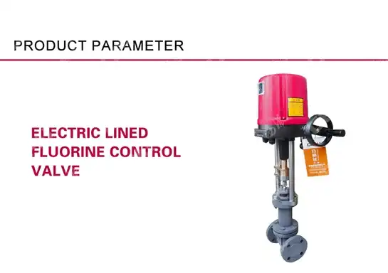
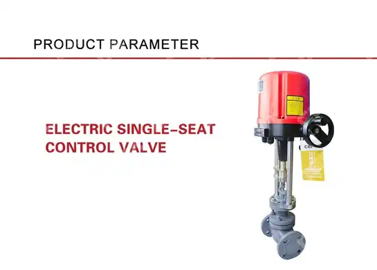
Contemporary Control Valve designs incorporate sophisticated geometry modifications that divide the total pressure drop into multiple smaller stages. Each stage reduces pressure incrementally, preventing any single location from dropping below the fluid's vapor pressure. This approach requires precise engineering calculations considering fluid properties, operating conditions, and valve geometry optimization. Manufacturers like CEPAI Group Co., LTD. have developed proprietary trim designs that combine multiple anti-cavitation techniques. Their electric Control Valve systems feature pressure-balanced spools with equal percentage or linear characteristics, specifically designed for demanding applications. With nominal diameters ranging from DN15-400mm and pressure ratings up to ANSI 600, these valves provide reliable performance across diverse industrial applications. The trim materials selection plays a crucial role in cavitation resistance. CEPAI's Control Valve products utilize high-grade stainless steel internals including 304, 316, and specialized surfacing materials that resist cavitation erosion. The company's quality management system ensures each valve meets strict performance standards through comprehensive testing protocols.
Installation and System Design Optimization
Proper Control Valve installation represents a critical factor in preventing cavitation and flashing problems. Alternative approaches include modifying pump systems, installing variable frequency drives, or adjusting impeller configurations to reduce pressure drops across valves. These system-level modifications often provide more cost-effective solutions than replacing existing Control Valve installations. Pipeline configuration significantly influences cavitation potential in Control Valve applications. Upstream piping should provide sufficient straight runs to ensure fully developed flow profiles entering the valve. Downstream piping design must accommodate pressure recovery patterns while preventing flow separation and recirculation zones that exacerbate cavitation conditions.
-
Upstream and Downstream Considerations
Upstream conditions affect Control Valve performance through pressure profile development and flow distribution patterns. Insufficient upstream pressure, inadequate straight pipe runs, or poorly designed fittings can create non-uniform velocity profiles that intensify cavitation potential. Engineers must consider these factors during system design phases to optimize overall performance. Downstream piping design requires careful attention to pressure recovery characteristics. Sudden expansions, sharp bends, or restrictive fittings can prevent proper pressure recovery, maintaining cavitation conditions well beyond the valve itself. Proper downstream design includes gradual expansions, minimal restrictions, and sufficient length for pressure stabilization. CEPAI Group's technical expertise extends beyond valve manufacturing to comprehensive system design support. Their engineering team provides pre-sales technical consultation and customized solution services, helping customers optimize entire piping systems for cavitation avoidance. This holistic approach ensures optimal Control Valve performance while minimizing installation and operational challenges.
Control Valve Selection Criteria and Specifications

Selecting appropriate Control Valve specifications requires comprehensive analysis of operating conditions, fluid properties, and performance requirements. Critical parameters include pressure drop ratios, flow coefficients, recovery factors, and cavitation indices. Engineers must balance these factors against cost considerations and maintenance requirements to achieve optimal solutions. Flow coefficient (Cv) calculations become significantly more complex in cavitation-prone applications. Standard sizing equations require modification factors accounting for two-phase flow effects, pressure recovery characteristics, and cavitation limitations. CEPAI Group's Control Valve products provide detailed technical specifications supporting accurate sizing calculations for challenging applications.
-
Material Selection and Durability Factors
Control Valve materials must withstand both normal operating conditions and potential cavitation effects. Body materials for CEPAI valves include WCB, CF8, and CF8M options providing excellent corrosion resistance and mechanical properties. Extended bonnets accommodate extreme temperature applications ranging from -40°C to -196°C, essential for cryogenic and low-temperature services. Internal component materials require special consideration for cavitation resistance. Stainless steel grades 316 and 316L offer superior cavitation erosion resistance compared to standard carbon steels. Specialized surfacing treatments and hardfacing applications provide additional protection in severe service conditions. CEPAI's manufacturing capabilities include comprehensive testing facilities ensuring product quality and performance. Their CNAS nationally recognized laboratory provides material analysis, dimensional inspection, and performance testing according to international standards. This quality assurance approach guarantees reliable Control Valve performance in demanding applications.
Monitoring and Maintenance Strategies
Effective cavitation prevention requires continuous monitoring of Control Valve performance indicators. Engineers use noise and vibration measurements to detect cavitation conditions before significant damage occurs. Modern monitoring systems provide real-time analysis of acoustic signatures, vibration patterns, and performance deviations indicating cavitation onset. Predictive maintenance programs for Control Valve systems incorporate multiple monitoring techniques including acoustic emission testing, vibration analysis, and performance trending. These approaches enable early detection of cavitation conditions while minimizing unnecessary maintenance interventions. CEPAI Group provides remote monitoring and intelligent service capabilities supporting advanced maintenance strategies.
-
Diagnostic Techniques and Early Warning Systems
Advanced diagnostic systems analyze multiple parameters simultaneously to identify cavitation conditions accurately. Acoustic monitoring detects characteristic frequency patterns associated with vapor bubble formation and collapse. Vibration analysis reveals mechanical effects of cavitation on valve components and connected piping systems. Performance monitoring compares actual Control Valve characteristics against baseline performance curves. Deviations in flow capacity, pressure drop relationships, or control responsiveness indicate potential cavitation problems requiring investigation. Modern control systems integrate these diagnostic capabilities providing operators with comprehensive cavitation monitoring tools. CEPAI's electric Control Valve systems incorporate sophisticated control signal processing supporting 4-20mA feedback signals with optional position indication. These capabilities enable integration with advanced plant control systems providing comprehensive cavitation monitoring and prevention capabilities.
Conclusion
Control Valve cavitation and flashing prevention requires comprehensive understanding of fluid dynamics principles, proper system design, appropriate valve selection, and effective monitoring strategies. Success depends on coordinating multiple factors including pressure management, material selection, trim design optimization, and maintenance planning throughout the entire system lifecycle.
Cooperate with CEPAI Group Co., LTD.
As a leading China Control Valve manufacturer and China Control Valve supplier, CEPAI Group Co., LTD. brings over 15 years of specialized expertise in high-end energy valve manufacturing. Located in Jiangsu Province's Jinhu Economic Development Zone, our 56,000 square meter facility represents China's most advanced Control Valve production capabilities. Our China Control Valve factory features the longest high-precision intelligent manufacturing flexible production line in the Asia Pacific region, ensuring exceptional durability and high-precision control performance for every Control Valve for sale.
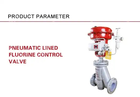
Our comprehensive product portfolio extends beyond electric low-temperature Control Valve systems to include pneumatic control valves, ball valves, butterfly valves, and specialized fluorine-lined valves. As a trusted China Control Valve wholesale partner, we maintain supplier qualifications with PetroChina, Sinopec, CNOOC, and major international energy companies. Our High Quality Control Valve products feature competitive Control Valve price structures while maintaining the highest performance standards through our ISO 9001, ISO 14001, and ISO 45001 certified quality management systems.
Partner with CEPAI Group Co., LTD. for your critical Control Valve applications and experience the advantages of working with a premier China Control Valve factory. Contact our technical experts at cepai@cepai.com to discuss your specific requirements and discover why industry leaders choose CEPAI for reliable, high-performance valve solutions worldwide.
FAQ
Q: What is the primary difference between Control Valve cavitation and flashing?
A: Cavitation involves vapor bubble formation and violent collapse causing damage, while flashing creates permanent vapor that doesn't collapse downstream.
Q: How can I detect early signs of cavitation in my Control Valve system?
A: Monitor for unusual noise, vibration, reduced flow capacity, and visible erosion damage on valve internals during routine inspections.
Q: What trim design features help prevent Control Valve cavitation?
A: Multi-stage pressure reduction, tortuous flow paths, and pressure-balanced designs effectively minimize cavitation formation in critical applications.
Q: Can system modifications eliminate cavitation without replacing the Control Valve?
A: Yes, adjusting upstream pressure, modifying pump operations, or installing pressure-sustaining valves downstream can effectively prevent cavitation conditions.
References
1. "Control Valve Handbook" by Emerson Process Management, Fourth Edition, featuring comprehensive cavitation analysis and prevention techniques for industrial applications.
2. "ISA Handbook of Control Valves" by International Society of Automation, providing authoritative guidance on valve selection, sizing, and cavitation prevention strategies.
3. "Valve Selection and Service Guide" by Crane Technical Paper No. 410, offering detailed engineering principles for cavitation analysis and prevention in control valve systems.
4. "Control Valve Sizing and Selection" by Jon F. Monsen, presenting advanced methodologies for cavitation prediction and mitigation in complex industrial processes.
_1745994800896.webp)
Get professional pre-sales technical consultation and valve selection services, customized solution services.

About CEPAI