How does a flow limiting valve work?
Understanding the intricate mechanisms behind flow control technology is essential for engineers and operators working across various industrial applications. Flow limiting valves represent a critical component in modern fluid control systems, serving as the gatekeepers that regulate and restrict fluid movement through pipelines and process systems. These sophisticated devices operate through precise mechanical principles that combine throttling mechanisms with responsive control elements to maintain predetermined flow rates regardless of upstream pressure variations. A flow regulating valve essentially functions as an intelligent barrier that automatically adjusts its internal geometry to compensate for changing system conditions, ensuring consistent fluid delivery while protecting downstream equipment from excessive flow rates that could cause damage or operational inefficiencies.
Types and Classifications of Flow Limiting Mechanisms
Pressure-Compensated Flow Control Systems
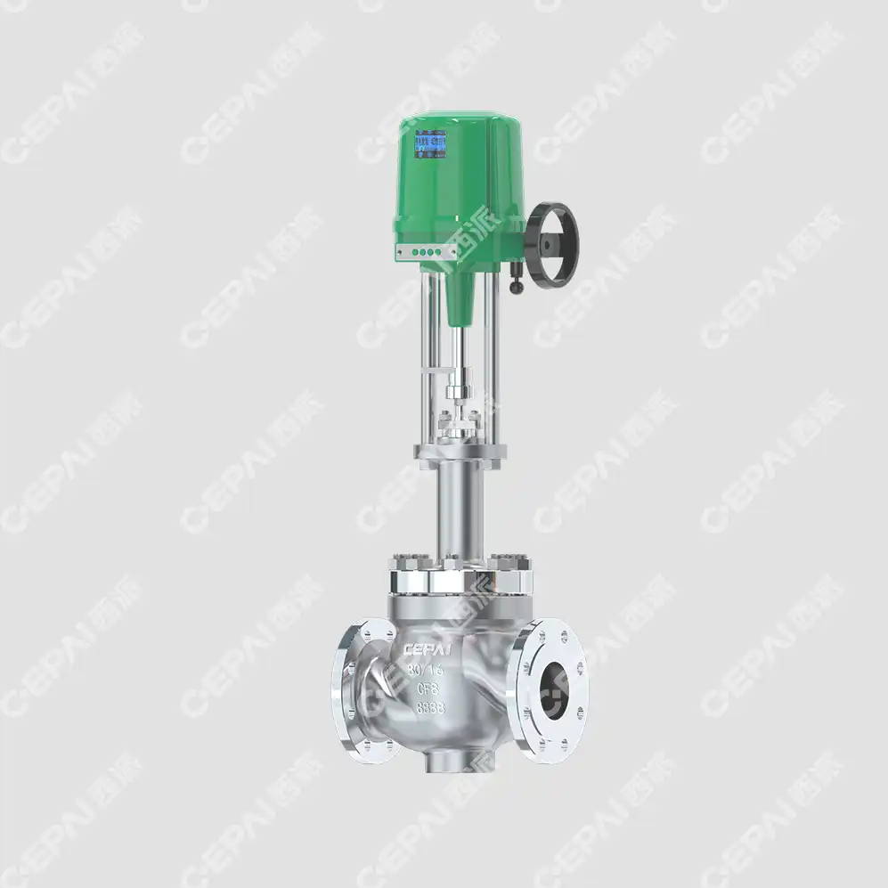
Pressure-compensated flow limiting valves represent the most sophisticated category of flow control devices, incorporating advanced internal mechanisms that automatically adjust to maintain consistent flow rates despite fluctuating upstream pressures. These systems utilize a unique dual-element design featuring both a flow restricting orifice and a pressure-compensating element that work in tandem to provide exceptional flow stability. The flow regulating valve in this configuration employs a spring-loaded compensator that responds to pressure differentials across the primary orifice, effectively modulating the effective flow area to counteract pressure variations. This sophisticated mechanism ensures that the downstream flow remains constant even when upstream pressures vary significantly, making these valves ideal for applications requiring precise flow control in variable pressure environments. The internal compensator typically consists of a movable spool or piston that is positioned by the balance between spring force and hydraulic pressure, creating a self-regulating system that requires no external control signals or power sources.
Fixed Orifice Flow Restrictors
Fixed orifice flow restrictors operate on the fundamental principle of creating a controlled pressure drop across a precisely machined opening, thereby limiting the maximum flow rate that can pass through the valve regardless of upstream pressure conditions. These devices feature a carefully engineered orifice plate or insert that creates a permanent restriction in the flow path, with the flow rate being determined by the orifice size, fluid properties, and pressure differential. The flow regulating valve design in fixed orifice systems relies on the square root relationship between pressure drop and flow rate, as described by Bernoulli's equation and the continuity principle. While these devices are simpler in construction compared to pressure-compensated systems, they require careful sizing calculations to ensure optimal performance across the expected operating range. The orifice geometry can vary significantly, from simple circular holes to complex shaped openings designed to optimize flow characteristics and minimize turbulence. These restrictors are particularly effective in applications where the upstream pressure remains relatively stable and precise flow control is required without the complexity of moving parts.
Variable Area Flow Control Devices
Variable area flow control devices incorporate adjustable restriction mechanisms that allow operators to modify the effective flow area during operation, providing flexibility in flow rate management without requiring valve replacement. These sophisticated systems typically employ tapered needle valves, adjustable orifices, or multi-position restriction plates that can be precisely positioned to achieve the desired flow characteristics. The flow regulating valve mechanism in variable area devices often includes graduated adjustment features, allowing for fine-tuning of flow rates to match specific process requirements. Advanced versions may incorporate remote actuation systems, enabling automatic adjustment based on process feedback signals or predetermined operating schedules. The internal design frequently features precision-machined components with specific taper angles and surface finishes designed to provide linear or characterized flow responses as the restriction area changes. These devices are particularly valuable in applications where process conditions vary over time or where different operating modes require different flow rates, providing operational flexibility while maintaining the reliability and accuracy expected from professional flow control equipment.
Operating Principles and Mechanical Functions
Hydraulic Force Balance Mechanisms
The hydraulic force balance mechanism forms the foundation of modern flow limiting valve operation, utilizing the fundamental principles of fluid mechanics to create self-regulating flow control systems. These mechanisms operate by establishing equilibrium between hydraulic forces acting on movable internal components and mechanical forces provided by springs or other preloading elements. The flow regulating valve design incorporates precisely calculated surface areas and spring constants to achieve the desired balance point, ensuring that the valve responds appropriately to changes in system pressure while maintaining the predetermined flow rate. The hydraulic forces are generated by pressure differentials acting on pistons, diaphragms, or spool surfaces, with the effective area of these surfaces being carefully engineered to provide the required force characteristics. As upstream pressure increases, the hydraulic force attempts to open the restriction further, but this is counteracted by the mechanical spring force and the geometry of the restriction itself, creating a stable operating point. The sophistication of these mechanisms lies in their ability to provide consistent performance across wide pressure ranges while compensating for temperature variations, fluid property changes, and wear over extended operating periods.
Throttling and Restriction Dynamics
The throttling and restriction dynamics within flow limiting valves involve complex fluid mechanical phenomena that determine the overall performance characteristics of these devices. When fluid passes through the restriction created by the valve's internal geometry, it experiences a controlled pressure drop that is directly related to the flow rate according to established hydraulic principles. The flow regulating valve creates this restriction through various means, including sharp-edged orifices, streamlined venturi sections, or adjustable needle valve configurations, each providing different flow characteristics and pressure loss profiles. The fluid acceleration through the restriction creates velocity increases and corresponding pressure decreases, as described by Bernoulli's principle, while the subsequent flow expansion and energy dissipation contribute to the overall pressure drop across the valve. Turbulence patterns, boundary layer effects, and fluid viscosity all influence the precise flow characteristics, requiring careful consideration during the valve design process. The restriction geometry must be optimized to provide stable flow control while minimizing adverse effects such as cavitation, noise generation, or excessive pressure loss that could impact overall system efficiency.
Response Characteristics and Control Stability
The response characteristics and control stability of flow limiting valves are critical factors that determine their effectiveness in maintaining consistent flow rates under varying operating conditions. These characteristics are governed by the dynamic interaction between the valve's mechanical components, the fluid properties, and the external system conditions that influence valve performance. The flow regulating valve must exhibit appropriate response times to pressure changes while avoiding oscillation or hunting behavior that could destabilize the flow control system. The valve's response is influenced by factors such as the mass and friction of moving components, the stiffness of spring elements, the damping provided by fluid flow, and the overall system impedance downstream of the valve. Properly designed flow limiting valves incorporate carefully tuned mechanical parameters that provide rapid response to legitimate system changes while filtering out noise and minor fluctuations that could cause unnecessary valve movement. The stability margin of the control system must be sufficient to handle normal operating variations while maintaining tight flow control tolerance, requiring sophisticated analysis of the closed-loop system dynamics during the design phase.
Applications and System Integration Considerations
Industrial Process Control Systems
Industrial process control systems rely heavily on flow limiting valves to maintain precise control over material and energy flows that are critical to product quality and operational efficiency. These applications span numerous industries including chemical processing, petroleum refining, power generation, and pharmaceutical manufacturing, where accurate flow control directly impacts product specifications and process safety. The flow regulating valve serves as a key component in complex control loops that may include temperature, pressure, and composition control elements, requiring careful integration to ensure optimal overall system performance. Modern industrial applications often demand flow control accuracy within narrow tolerance bands while operating under challenging conditions such as high temperatures, corrosive environments, or varying fluid compositions that can affect valve performance over time. The integration of flow limiting valves into distributed control systems requires consideration of signal compatibility, response time matching, and fail-safe operation modes that protect both the process and equipment in the event of system malfunctions. Advanced industrial systems may incorporate predictive maintenance capabilities and real-time performance monitoring to optimize valve operation and schedule maintenance activities based on actual performance degradation rather than arbitrary time intervals.

Hydraulic and Pneumatic Circuit Applications
Hydraulic and pneumatic circuit applications represent a significant market for flow limiting valves, where precise control of actuator speeds and force characteristics depends on accurate flow regulation throughout the fluid power system. These applications require flow regulating valve designs that can handle the unique characteristics of compressed air and hydraulic fluids while providing consistent performance across varying load conditions and operating pressures. The valve must accommodate the compressibility effects present in pneumatic systems while providing the precision required for smooth actuator operation and accurate positioning control. Hydraulic applications often involve higher pressures and power densities, requiring robust construction and materials capable of withstanding continuous high-pressure operation without degradation. The integration of flow limiting valves into hydraulic and pneumatic circuits requires careful consideration of system dynamics, including the effects of fluid compressibility, line capacitance, and actuator characteristics on overall system response. Modern fluid power applications increasingly demand energy efficiency improvements, leading to the development of flow limiting valves with reduced pressure losses and improved control characteristics that minimize power consumption while maintaining performance standards.
Safety and Emergency Shutdown Systems
Safety and emergency shutdown systems represent critical applications where flow limiting valves play essential roles in protecting personnel, equipment, and the environment during abnormal operating conditions. These systems require flow regulating valve designs that provide reliable operation under extreme conditions while maintaining fail-safe characteristics that ensure proper system response even during component failures. The valve design must incorporate redundant sealing systems, robust construction materials, and simplified mechanical designs that minimize the potential for failure modes that could compromise safety system functionality. Emergency shutdown applications often require fast-acting valve response combined with controlled flow limitation to prevent system damage during rapid shutdown sequences, requiring careful balance between response speed and flow control accuracy. The integration of flow limiting valves into safety instrumented systems requires compliance with international safety standards such as IEC 61508 and IEC 61511, demanding rigorous design validation, testing protocols, and documentation requirements that demonstrate the valve's safety integrity level capabilities. These applications also require consideration of common cause failures, systematic failures, and the overall safety instrumented system architecture to ensure that the flow limiting valve contributes appropriately to the overall safety function reliability.
Conclusion
Flow limiting valves represent sophisticated engineering solutions that combine fundamental fluid mechanics principles with precision mechanical design to achieve reliable flow control across diverse industrial applications. These devices operate through carefully balanced hydraulic and mechanical forces that automatically adjust to maintain predetermined flow rates while accommodating system pressure variations and changing operating conditions. The effectiveness of modern flow regulating valve technology lies in the thoughtful integration of throttling mechanisms, force balance systems, and responsive control elements that work together to provide stable, accurate flow control without requiring external power sources or complex control systems.
Ready to optimize your flow control systems with industry-leading valve technology? CEPAI Group combines exceptional durability with high-precision control performance, backed by extensive R&D investments and comprehensive quality certifications including ISO 9001, API standards, and CE marking. Our experienced engineering team provides complete pre-sales technical consultation, customized solutions, and comprehensive after-sales support to ensure your flow control applications achieve optimal performance. From initial valve selection through installation, commissioning, and ongoing maintenance, we deliver the expertise and reliability your operations demand. Contact our technical specialists today at cepai@cepai.com to discuss your specific flow control requirements and discover how our advanced flow regulating valve solutions can enhance your system performance while reducing operational costs and maintenance requirements.
References
1. Miller, R.W. (2019). "Flow Measurement Engineering Handbook: Advanced Principles and Applications in Industrial Flow Control Systems." Technical Publishing International.
2. Thompson, J.K. & Anderson, M.L. (2020). "Hydraulic Control Systems: Theory and Application of Flow Regulating Devices in Modern Industrial Applications." Mechanical Engineering Press.
3. Chen, L.P. (2018). "Valve Technology and Control Systems: Comprehensive Guide to Flow Limitation and Pressure Regulation Mechanisms." International Valve Association.
4. Rodriguez, C.A. & Williams, D.R. (2021). "Industrial Process Control: Advanced Flow Control Strategies and Valve Selection Criteria for Critical Applications." Process Engineering Quarterly, Vol. 45, No. 3.
5. Kumar, S. & Petrov, A.N. (2019). "Fluid Mechanics and Control Valve Design: Theoretical Foundations and Practical Implementation of Flow Limiting Technologies." Cambridge Technical Publishers.
6. Brown, K.M., Lee, H.S. & Taylor, P.J. (2020). "Safety Instrumented Systems and Flow Control: Design Principles for Emergency Shutdown and Process Safety Applications." Safety Engineering International.

Get professional pre-sales technical consultation and valve selection services, customized solution services.

About CEPAI
