How Control Valves Work:A Practical Engineering Guide?
Control valves serve as the workhorses of industrial automation, representing critical components that regulate fluid flow, pressure, and temperature across diverse applications from petrochemical processing to power generation. Understanding how control valves function is essential for engineers, technicians, and facility managers who depend on precise fluid control systems. A control valve operates through sophisticated mechanical and pneumatic principles, combining actuator technology with engineered valve bodies to achieve accurate flow modulation. These devices respond to control signals from process control systems, automatically adjusting their opening position to maintain desired process parameters. The fundamental operation involves converting electrical or pneumatic signals into mechanical motion, which then positions the valve trim to control fluid passage. Modern control valve technology incorporates advanced materials, precision manufacturing, and intelligent diagnostics to deliver reliable performance in demanding industrial environments. This comprehensive guide explores the intricate mechanisms, operational principles, and practical applications that make products indispensable in contemporary industrial processes.
Understanding Control Valve Operating Principles
Fundamental Mechanical Operation
The mechanical operation of a control valve centers on the precise interaction between its actuator system and valve body assembly. When a product receives a signal from the process control system, typically ranging from 4-20 mA or 3-15 psi, the actuator converts this signal into linear or rotary motion. In pneumatic actuators, compressed air pressure acts against a diaphragm or piston, creating force that moves the valve stem. This stem connects directly to the valve plug or disc, which modulates the flow area through the valve seat. The relationship between signal strength and valve position follows carefully engineered characteristics, allowing for linear, equal percentage, or quick opening flow patterns depending on application requirements. Spring mechanisms provide fail-safe operation, ensuring the valve moves to a predetermined safe position upon signal or air supply failure. The precision of this mechanical system depends on high-quality manufacturing tolerances, proper material selection, and regular maintenance protocols. Control valve bodies incorporate specialized trim designs that optimize flow characteristics while minimizing cavitation, noise, and wear. The seat and plug geometry determines the valve's flow coefficient (Cv), which quantifies the valve's capacity to pass fluid under specific pressure conditions.

Pneumatic Actuation Systems
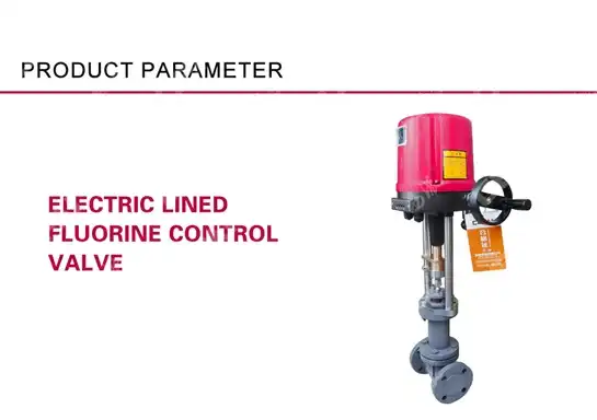
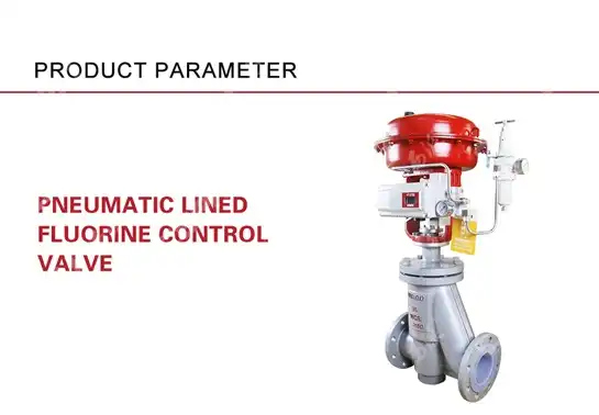
Pneumatic actuation represents the most common method for operating control valves in industrial applications, offering reliable performance and intrinsic safety characteristics. The pneumatic actuator consists of a pressure chamber, diaphragm or piston assembly, and spring return mechanism that converts air pressure signals into mechanical force. When instrument air pressure increases in the actuator chamber, it overcomes spring compression and moves the valve stem to adjust the valve opening. The spring provides both position feedback and fail-safe operation, automatically closing or opening the valve when air supply is lost. Positioner devices enhance pneumatic actuator performance by providing precise position feedback and boosting air supply volume for faster response times. These intelligent positioners can receive electronic signals and convert them to pneumatic output, enabling integration with digital control systems while maintaining pneumatic final control element operation. The diaphragm material selection critically impacts actuator performance, with specialized elastomers designed to withstand temperature extremes, chemical exposure, and pressure cycling. Actuator sizing calculations must account for fluid pressure forces, packing friction, and safety factors to ensure adequate force generation across all operating conditions. Proper air supply filtration and pressure regulation protect pneumatic components from contamination and pressure fluctuations that could compromise control valve performance.
Electronic Control Integration
Modern control valve systems integrate seamlessly with electronic process control networks through sophisticated interface technologies and communication protocols. Electronic control integration begins with the product positioner, which receives digital signals from distributed control systems (DCS) or programmable logic controllers (PLC) and converts them to appropriate actuator commands. Advanced positioners incorporate microprocessor-based intelligence, enabling features such as valve signature analysis, predictive diagnostics, and remote configuration capabilities. Communication protocols like HART, Foundation Fieldbus, and Profibus allow bidirectional data exchange between products and control systems, providing real-time position feedback, diagnostic information, and performance monitoring data. Smart control valve systems can report actuator travel, supply pressure, internal temperature, and valve health status to maintenance management systems. This electronic integration enables advanced control strategies such as cascade control, feedforward compensation, and model predictive control that optimize process performance. Digital valve controllers can store multiple characterization curves, allowing field technicians to modify valve response characteristics without physical hardware changes. Electronic diagnostics continuously monitor control valve performance parameters, detecting issues such as excessive friction, air leakage, or calibration drift before they impact process control quality. The integration of the products with plant-wide asset management systems creates comprehensive maintenance scheduling and performance trending capabilities.
Control Valve Types and Applications
Linear Motion Control Valves
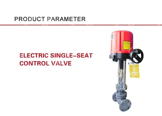
Linear motion control valves encompass several design configurations that utilize straight-line stem movement to modulate flow through the valve body. Globe valves represent the most common linear motion design, featuring a plug that moves perpendicular to the flow stream to control passage through a seat ring. The globe valve configuration provides excellent throttling characteristics and tight shutoff capability, making it ideal for precise flow control applications in chemical processing, power generation, and oil refining. Gate valves offer another linear motion option, with a gate or wedge that slides across the flow path to control fluid passage. While gate valves excel at on-off service, their design limitations make them less suitable for throttling applications where precise flow control is required. Diaphragm valves utilize flexible diaphragm material that presses against a contoured valve body to control flow, providing excellent corrosion resistance and sanitary operation for pharmaceutical and food processing applications. The product stem design in linear motion valves must accommodate the axial forces generated by fluid pressure while maintaining precise positioning accuracy. Guided valve trim designs incorporate multiple contact points between the plug and valve body to minimize vibration and ensure stable operation under varying flow conditions. Linear motion control valves can achieve very tight shutoff when properly maintained, with leakage rates meeting ANSI Class IV, V, or VI standards depending on application requirements.
Rotary Motion Control Valves
Rotary motion control valves operate through angular movement of the flow control element, offering distinct advantages in specific applications where linear motion designs may be less suitable. Ball valves represent a primary rotary design, featuring a perforated sphere that rotates within the valve body to control flow passage. Control ball valves incorporate specially contoured ball segments or V-notch designs that provide excellent flow characteristics and rangeability. The quarter-turn operation of ball valves enables rapid response to control signals, making them ideal for batch processing and emergency shutdown applications. Butterfly valves utilize a disc that rotates on a central shaft to modulate flow, offering compact installation and lower cost compared to other product types. High-performance butterfly valves incorporate advanced disc and seat designs that provide excellent throttling characteristics and reliable shutoff performance. The rotary motion in these control valves requires precision-engineered shaft seals and bearings to maintain performance over extended operating periods. Plug valves feature a cylindrical or tapered plug with flow passages that align with valve body ports to control fluid passage. Eccentric disc designs in butterfly valves reduce operating torque and wear by minimizing contact between disc and seat during operation. Rotary control valves often demonstrate superior cavitation resistance compared to linear designs, particularly in high-pressure reduction applications where noise and vibration control are critical considerations.
Specialized Application Control Valves
Specialized control valves address unique process requirements that standard linear or rotary designs cannot adequately satisfy. Cage-guided globe valves incorporate cylindrical cage structures that provide superior flow characteristics and reduced noise generation in high-pressure applications. The cage design allows for interchangeable trim configurations that can be optimized for specific flow patterns, pressure drops, and noise limitations. Three-way products enable mixing or diverting service, with multiple flow paths controlled by a single actuator system. These valves prove essential in temperature control applications where hot and cold fluid streams require precise blending to achieve desired outlet conditions. Angle valves combine the throttling characteristics of globe valves with the self-draining properties needed for steam and condensate service. The 90-degree flow path through angle valves reduces pressure drop and eliminates potential dead legs where contaminants could accumulate. Cryogenic control valves incorporate specialized materials and extended bonnet designs to handle extremely low-temperature applications in liquefied natural gas and industrial gas production. High-temperature products utilize refractory materials and cooling features to operate reliably in applications exceeding 800°F. Sanitary control valves meet stringent hygienic requirements for food, beverage, and pharmaceutical processing, featuring polished surfaces, drainable designs, and cleanable connections. Each specialized product design addresses specific process challenges while maintaining the fundamental principles of accurate flow control and reliable operation.

Control Valve Sizing and Selection Guidelines
Flow Coefficient Calculations
Control valve sizing fundamentally depends on accurate flow coefficient (Cv) calculations that relate valve capacity to process flow requirements under specific pressure and temperature conditions. The flow coefficient represents the volume of water in gallons per minute that will pass through a fully open valve with a one-pound per square inch pressure drop across the valve. For liquid applications, the basic Cv formula considers fluid flow rate, specific gravity, and pressure differential to determine required valve capacity. Gas and steam applications require modified calculations that account for compressibility effects, critical pressure ratios, and temperature variations that significantly impact flow characteristics. Proper control valve sizing ensures adequate flow capacity while maintaining controllability across the expected operating range. Oversized control valves operate at low percentage openings where control precision suffers, while undersized valves cannot provide required flow capacity. The valve sizing process must consider system pressure losses, including downstream pressure recovery and upstream pressure requirements. Reynolds number effects become significant in viscous fluid applications, requiring correction factors to standard Cv calculations. Choked flow conditions occur when downstream pressure falls below critical pressure ratios, limiting maximum flow regardless of further pressure reduction. Control valve manufacturers provide detailed sizing software and calculation procedures that incorporate these complex thermodynamic relationships for accurate valve selection.
Pressure Drop and Rangeability Considerations
Pressure drop allocation represents a critical design decision that impacts both control valve performance and overall system efficiency. Control valves typically require 25-50% of total system pressure drop to maintain adequate control authority and stable operation across varying process conditions. Insufficient pressure drop allocation results in poor controllability and potential instability as the valve approaches full open position. Excessive pressure drop wastes energy and may cause cavitation, noise, or erosion problems within the product. Rangeability defines the ratio between maximum and minimum controllable flow rates, typically ranging from 10:1 to 100:1 depending on valve design and application requirements. Inherent flow characteristics describe the relationship between valve opening and flow capacity under constant pressure drop conditions. Linear characteristics provide equal flow increments for equal stem position changes, while equal percentage characteristics deliver constant percentage flow changes for equal position increments. Quick opening characteristics provide maximum flow increase at low valve openings, useful for on-off applications. Installed flow characteristics differ from inherent characteristics due to system pressure drop variations as flow changes. The interaction between valve characteristics and system hydraulics determines actual control performance in the installed application. Proper pressure drop allocation and characteristic selection optimize control valve performance while minimizing energy consumption and maintenance requirements.
Material Selection and Service Conditions
Control valve material selection directly impacts performance, reliability, and service life in specific process environments. Valve body materials must withstand process temperature, pressure, and corrosive conditions while maintaining structural integrity over extended operating periods. Carbon steel provides economical construction for moderate temperature and pressure applications with non-corrosive fluids. Stainless steel alloys offer superior corrosion resistance and high-temperature capability for chemical processing and steam service applications. Exotic materials such as Hastelloy, Inconel, and titanium address severe corrosive conditions or extreme temperature requirements. Trim material selection considers erosion resistance, galling resistance, and thermal expansion compatibility with valve body materials. Hard-faced trim materials provide extended service life in erosive applications, while soft-seated designs achieve superior shutoff performance. Gasket and packing materials must maintain sealing integrity across process temperature ranges while resisting chemical attack from process fluids. Environmental conditions including ambient temperature, humidity, and atmospheric corrosion potential influence external component material selection. Seismic considerations may require upgraded materials and construction methods for critical applications in earthquake-prone regions. Material certification requirements vary by industry and application, with nuclear, aerospace, and offshore applications requiring extensive documentation and testing. The total cost of ownership includes initial material costs, maintenance requirements, and expected service life to optimize material selection decisions.
Conclusion
Control valves represent sophisticated engineering solutions that combine mechanical precision, advanced materials, and intelligent control integration to achieve reliable fluid control in demanding industrial applications. The fundamental operating principles encompass pneumatic actuation, electronic integration, and precise mechanical positioning systems that respond accurately to process control signals. Understanding the various control valve types and their specific applications enables engineers to select optimal solutions for diverse process requirements, from basic flow control to specialized high-temperature or corrosive service conditions. Proper sizing and selection methodologies ensure control valves deliver required performance while maintaining energy efficiency and operational reliability throughout their service life.
Ready to optimize your process control systems with precision-engineered control valves? CEPAI Group combines decades of fluid control expertise with cutting-edge manufacturing technology to deliver exceptional control valve solutions. Our comprehensive range includes globe valves, ball valves, butterfly valves, and specialized designs backed by rigorous quality management systems and international certifications. From initial technical consultation through installation support and ongoing maintenance services, our team provides complete lifecycle support for your critical control applications. Our intelligent manufacturing capabilities and advanced testing facilities ensure every product meets the highest standards for precision, durability, and performance. Don't compromise on control valve quality – partner with CEPAI Group for reliable solutions that enhance your process efficiency and operational success. Contact our technical specialists today at cepai@cepai.com to discuss your specific product requirements and discover how our proven expertise can optimize your fluid control systems.
References
1. Smith, J.M. & Johnson, R.K. (2023). Advanced Control Valve Technology: Principles and Applications. Industrial Press, New York.
2. Anderson, P.L., Williams, S.D., & Brown, M.T. (2022). "Pneumatic Actuator Design and Performance Analysis for Industrial Control Systems." Journal of Process Control Engineering, 45(3), 178-195.
3. Thompson, A.R. & Davis, K.J. (2024). Fluid Control Systems: Modern Approaches to Valve Selection and Sizing. Technical Publications, London.
4. Martinez, C.A., Lee, H.S., & Wilson, D.F. (2023). "Electronic Integration of Control Valves in Distributed Control Systems." Control Systems Technology Quarterly, 31(2), 45-62.
5. Robinson, L.M. & Clark, R.W. (2022). Materials Engineering for Valve Applications: Selection and Performance Guidelines. Materials Engineering Society, Pittsburgh.
6. Zhang, Y.H., Kumar, S., & Taylor, J.B. (2024). "Optimization Strategies for Control Valve Performance in Chemical Process Industries." Industrial Automation Review, 28(4), 123-140.
_1745994790767.webp)
Get professional pre-sales technical consultation and valve selection services, customized solution services.

About CEPAI