A Step-by-Step Guide to Calibrating a Control Valve
Picture this scenario: Your industrial process is running smoothly when suddenly, product quality drops, energy consumption spikes, and production efficiency plummets. The culprit? An improperly calibrated Control Valve that's silently sabotaging your entire operation. This comprehensive guide provides the essential knowledge and step-by-step procedures for calibrating a Control Valve effectively, ensuring optimal performance, safety, and cost efficiency in your industrial processes. Whether you're dealing with pressure regulation, flow control, or temperature management, proper Control Valve calibration is the foundation of reliable process control.
Understanding Control Valve Calibration Fundamentals
-
What Makes Control Valve Calibration Critical?
Control Valve calibration represents the cornerstone of industrial process optimization, directly impacting operational efficiency, safety protocols, and economic performance. When a Control Valve operates without proper calibration, it creates cascading effects throughout the entire system, leading to process instability, increased maintenance costs, and potential safety hazards. Modern industrial facilities rely heavily on precise process control, where even minor deviations in Control Valve performance can result in significant production losses, quality issues, and regulatory compliance problems. The calibration process establishes the relationship between the input signal and the valve's actual position, ensuring that the Control Valve responds accurately to control system commands. This relationship is fundamental for maintaining process variables within specified limits, optimizing energy consumption, and preventing equipment damage. Advanced Control Valve systems incorporate smart positioners, digital communication protocols, and diagnostic capabilities that enhance calibration accuracy and provide real-time performance monitoring.
-
Essential Components and Their Roles
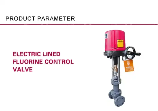
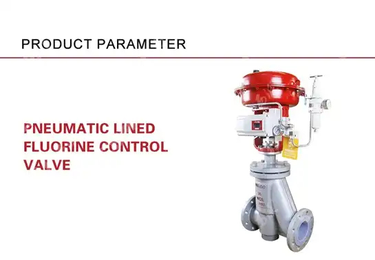
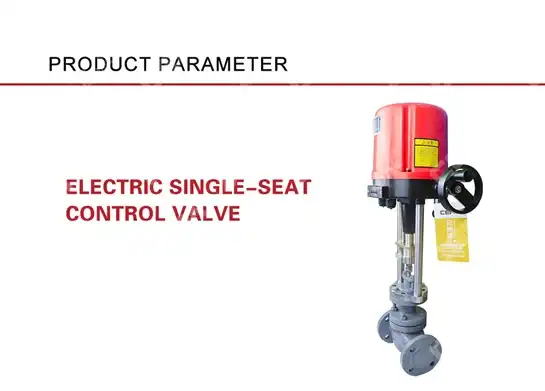
Every Control Valve system comprises several interconnected components that work together to achieve precise process control. The valve body contains the flow control element, which modulates fluid flow based on the actuator's position. The actuator provides the mechanical force necessary to position the valve, whether pneumatic, electric, or hydraulic. The positioner acts as the intelligent interface between the control system and the actuator, converting control signals into precise valve positions while compensating for friction, pressure variations, and other disturbances. Modern smart positioners incorporate advanced features such as digital communication capabilities, built-in diagnostics, and automatic calibration routines. These devices can communicate using protocols like HART, Foundation Fieldbus, or Profibus, providing real-time feedback on valve position, actuator pressure, temperature, and other critical parameters. The integration of these components creates a sophisticated control system that requires systematic calibration procedures to ensure optimal performance and reliability throughout its operational lifetime.
Pre-Calibration Preparation and Safety Measures
-
Safety Protocols and System Isolation
Before initiating any Control Valve calibration procedure, establishing comprehensive safety protocols is paramount to protect personnel and prevent process disruptions. The calibration process requires system isolation, which involves shutting down the affected process section, depressurizing lines, and implementing proper lockout/tagout procedures. Personnel must wear appropriate personal protective equipment, including safety glasses, gloves, and hearing protection when working in industrial environments. Process isolation procedures vary depending on the application and system complexity. For critical applications, coordination with operations personnel ensures that bypass systems are operational and alternative control strategies are in place. The Control Valve's service conditions, including pressure, temperature, and fluid characteristics, must be thoroughly documented before beginning calibration work. This information is essential for selecting appropriate calibration equipment and establishing safe working parameters.
-
Required Tools and Equipment
Professional Control Valve calibration requires specialized tools and equipment designed for industrial applications. A calibrated pressure source capable of providing the actuator's operating pressure range is essential, along with accurate pressure gauges or digital manometers for monitoring supply and output pressures. HART communicators or other digital communication devices enable interaction with smart positioners, allowing access to configuration parameters and diagnostic information. Additional equipment includes precision current sources for generating 4-20 mA signals, multimeters for electrical measurements, and valve position indicators for mechanical verification. Calibration documentation tools, including data loggers or computer-based calibration software, facilitate accurate record-keeping and compliance with quality standards. The selection of calibration equipment must consider the specific requirements of the Control Valve system, including communication protocols, pressure ranges, and environmental conditions.
Step-by-Step Control Valve Calibration Procedure
-
Initial System Verification and Documentation
The calibration process begins with comprehensive system verification and documentation of existing conditions. Record the Control Valve's current configuration, including model numbers, serial numbers, and software versions for smart devices. Document the process conditions, including operating pressure, temperature ranges, and fluid properties that affect valve performance. This baseline information is crucial for troubleshooting and future maintenance activities. Perform initial functionality tests to assess the Control Valve's current performance and identify any obvious issues before proceeding with calibration. Check for proper air supply pressure, electrical connections, and communication links with the control system. Verify that the valve travels through its full range without binding, excessive noise, or irregular movement patterns. These preliminary checks help identify mechanical problems that could affect calibration accuracy and should be resolved before proceeding.
-
Zero and Span Adjustment Procedures
Zero adjustment establishes the valve's closed position in response to the minimum input signal, typically 4 mA in analog systems. Begin by applying the minimum input signal to the positioner and verifying that the Control Valve moves to its fully closed position. If adjustment is necessary, access the positioner's zero adjustment mechanism, which may be a mechanical screw or digital parameter depending on the device type. Make incremental adjustments while monitoring valve position until the desired closed position is achieved. Span adjustment defines the valve's full open position in response to the maximum input signal, usually 20 mA. Apply the maximum input signal and verify that the Control Valve reaches its fully open position. Adjust the span setting as needed to achieve proper full-scale travel. The relationship between zero and span settings is interdependent, so adjustments to one parameter may affect the other. This iterative process requires patience and systematic approach to achieve optimal calibration results.
-
Linearity and Response Time Testing
Linearity testing verifies that the Control Valve's position responds proportionally to input signal changes throughout its operating range. Apply incremental input signals at 25%, 50%, and 75% of full scale, recording the corresponding valve positions. Calculate the deviation from theoretical linear response and compare against acceptable tolerances. Modern smart positioners often include built-in linearity compensation algorithms that can be adjusted to minimize these deviations. Response time testing measures how quickly the Control Valve responds to step changes in input signal. Apply step changes between different signal levels and measure the time required for the valve to reach its new position within acceptable settling criteria. Fast response times are generally desirable but must be balanced against system stability requirements. Overly aggressive tuning can cause oscillation or hunting behavior that degrades control performance.
-
Hysteresis and Repeatability Verification
Hysteresis represents the difference in valve position when approaching the same signal level from different directions. Test hysteresis by increasing the input signal to various levels and then decreasing it to the same points, measuring position differences at each level. Excessive hysteresis indicates mechanical problems such as packing friction, actuator wear, or positioner issues that may require maintenance or adjustment. Repeatability testing verifies that the Control Valve consistently returns to the same position for identical input signals. Perform multiple cycles between different signal levels and measure position variations for each signal point. Modern Control Valve systems should demonstrate excellent repeatability, typically within 0.1% of full scale or better. Poor repeatability often indicates mechanical wear, contamination, or calibration drift that requires corrective action.
Advanced Calibration Techniques for Smart Control Valves
-
Digital Communication and Configuration
Smart Control Valves equipped with digital communication capabilities offer advanced calibration features that significantly improve accuracy and efficiency. HART communication enables access to detailed configuration parameters, diagnostic information, and calibration functions through handheld communicators or asset management software. These tools provide guided calibration procedures that automate many manual steps and reduce the potential for human error. Foundation Fieldbus and Profibus systems offer even more sophisticated capabilities, including continuous position feedback, advanced diagnostics, and integration with plant-wide asset management systems. These digital protocols enable remote calibration and monitoring capabilities that reduce maintenance costs and improve system reliability. The calibration process for digital systems often includes automatic stroke testing, signature analysis, and predictive maintenance features that extend equipment life and optimize performance.
-
Signature Analysis and Diagnostic Testing
Modern smart positioners incorporate signature analysis capabilities that provide detailed insights into Control Valve performance characteristics. This technology analyzes the relationship between actuator pressure and valve position throughout the stroke, creating a unique signature that reveals mechanical condition and potential problems. Signature analysis can detect issues such as packing friction changes, seat damage, or actuator degradation before they cause significant performance problems. Diagnostic testing extends beyond basic calibration to include comprehensive performance evaluation of all system components. Smart positioners continuously monitor parameters such as supply pressure stability, actuator leakage, temperature effects, and communication integrity. This diagnostic information helps maintenance personnel optimize calibration intervals, predict maintenance requirements, and improve overall system reliability.
Troubleshooting Common Control Valve Calibration Issues
-
Mechanical Problems and Solutions
Control Valve calibration problems often stem from mechanical issues that affect valve performance and calibration accuracy. Packing friction represents one of the most common problems, causing irregular valve movement, poor repeatability, and excessive hysteresis. This condition typically results from improper packing adjustment, wear, or contamination that increases friction between moving parts. Solution involves packing adjustment, replacement, or cleaning depending on the severity of the condition. Actuator problems, including diaphragm wear, spring degradation, or contamination, can significantly impact calibration results. These issues manifest as sluggish response, position drift, or inability to reach full travel limits. Systematic diagnosis involves checking actuator air supply quality, verifying spring tension, and inspecting diaphragm condition. Resolution may require actuator overhaul, component replacement, or air supply system improvements to restore proper performance.
-
Electronic and Pneumatic System Issues
Electronic problems in Control Valve systems can cause calibration difficulties and erratic performance. Signal interference, ground loops, or power supply issues may affect the accuracy of input signals and position feedback. Systematic troubleshooting involves verifying signal integrity, checking power supply stability, and ensuring proper grounding and shielding of communication cables. Installation of signal isolators or filters may be necessary to eliminate interference sources. Pneumatic system problems, including air supply contamination, pressure instability, or leakage, directly affect Control Valve performance and calibration accuracy. Water or oil contamination in the air supply can cause positioner malfunctions, actuator problems, and premature component wear. Regular air quality monitoring, filter maintenance, and dryer system operation are essential for maintaining optimal pneumatic system performance and ensuring reliable calibration results.
Conclusion
Proper Control Valve calibration is fundamental to achieving optimal industrial process performance, safety, and efficiency. This comprehensive guide has outlined the essential procedures, safety considerations, and advanced techniques necessary for successful calibration. Regular calibration maintains system reliability, reduces operational costs, and ensures compliance with industry standards and regulations.
Cooperate with CEPAI Group Co., LTD.
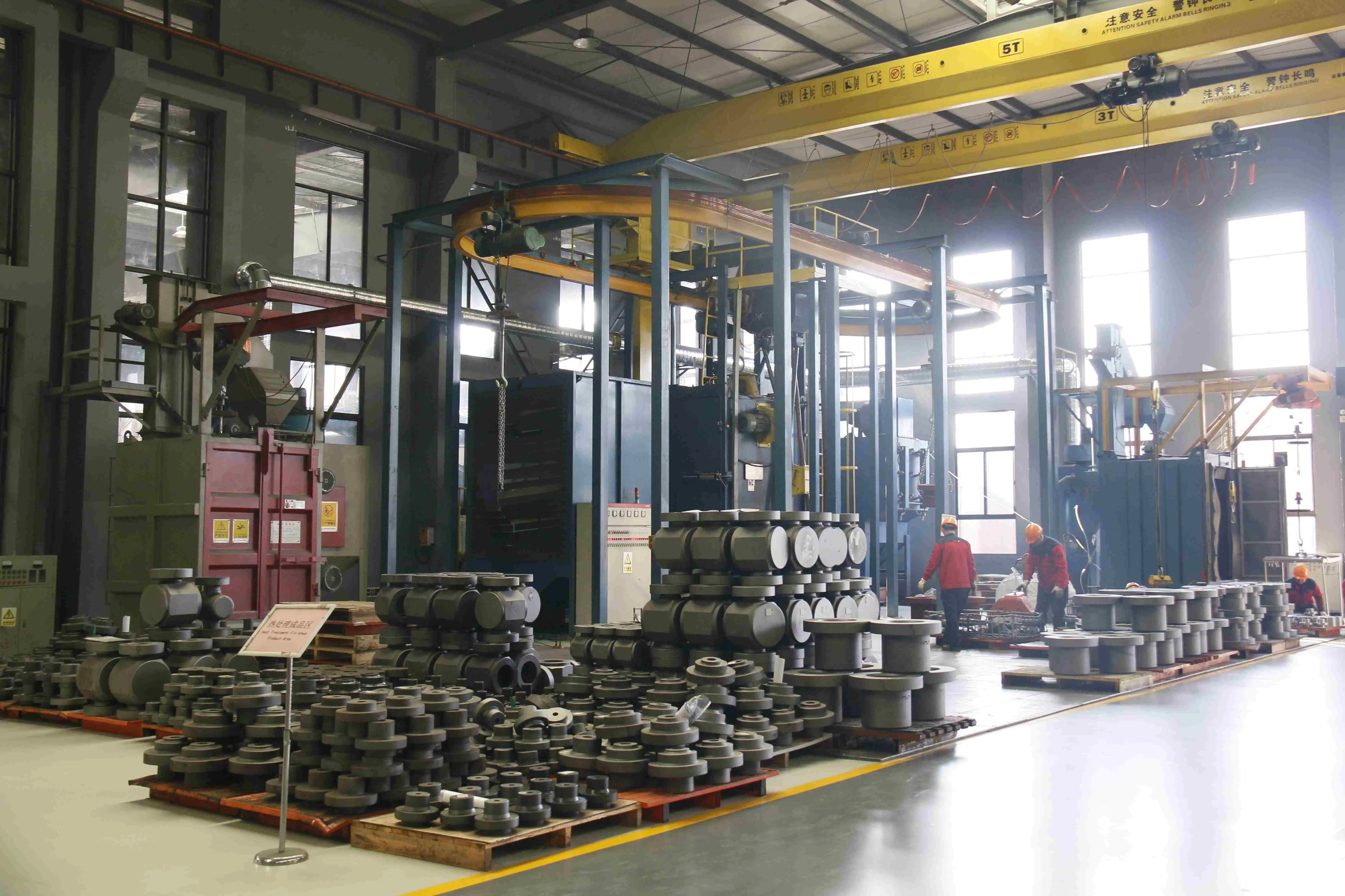
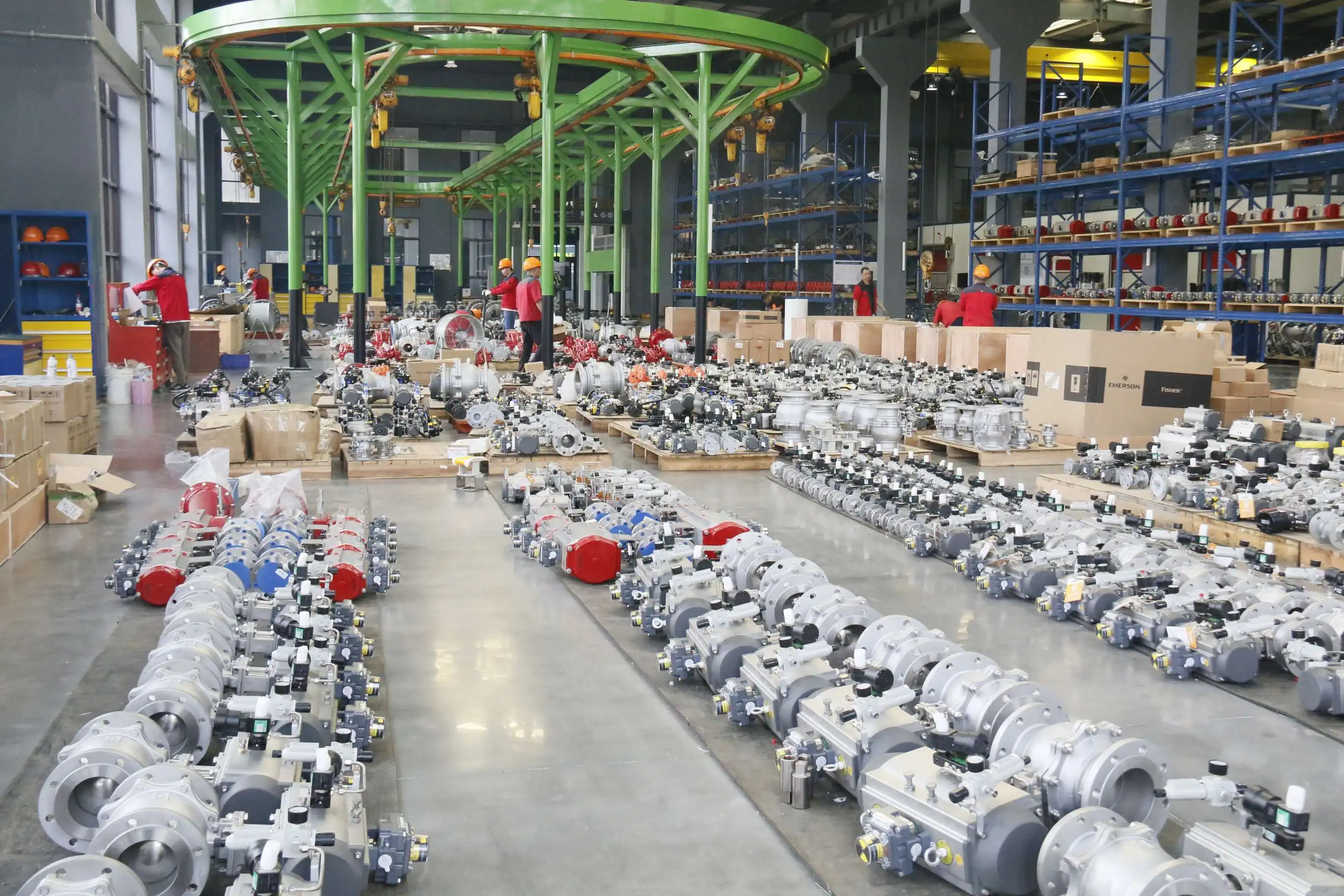
CEPAI Group Co., Ltd. stands as a leading China Control Valve manufacturer, established in January 2009 with extensive expertise in high-end energy valve manufacturing. As a national high-tech enterprise and specialized "little giant" company, CEPAI has earned recognition as a Jiangsu Smart Factory and Internet benchmarking factory, winning the Mayor Quality Award in 2022. The company operates state-of-the-art facilities spanning 56,000 square meters, featuring the longest high-precision intelligent manufacturing flexible production line in the Asia Pacific region.
Our comprehensive certifications including API Q1, API 6A, API 6D, ISO 9001, and Control Valve SIL certification demonstrate our commitment to quality and safety standards. As a trusted China Control Valve supplier, we serve major clients including PetroChina, Sinopec, CNOOC, and China Datang Group. Our intelligent manufacturing capabilities, backed by 156 million yuan in advanced equipment investment, ensure High Quality Control Valve production with exceptional precision and reliability.
Whether you need standard or customized Control Valve solutions, our experienced engineering team provides comprehensive pre-sales consultation, installation support, and after-sales service. Our Control Valve for sale includes sleeve-type regulating valves, throttle valves, and emergency shut-off valves designed for critical applications. For competitive Control Valve price quotes and technical specifications, contact our team at cepai@cepai.com. Partner with CEPAI Group, your trusted China Control Valve wholesale provider, for reliable, high-performance valve solutions that meet the most demanding industrial applications.
FAQ
Q: How often should Control Valve calibration be performed?
A: Control Valve calibration frequency depends on application criticality, operating conditions, and regulatory requirements. Generally, perform calibration every 6-12 months for critical applications, annually for standard applications, and whenever performance degradation is suspected.
Q: What are the signs that a Control Valve needs recalibration?
A: Common signs include poor process control, increased energy consumption, unusual noise or vibration, inability to reach setpoints, and excessive controller output changes to maintain process variables.
Q: Can Control Valve calibration be performed while the process is running?
A: Online calibration is possible with certain smart valve systems that have bypass capabilities or redundant control paths. However, most calibration procedures require process isolation for safety and accuracy reasons.
Q: What documentation is required for Control Valve calibration?
A: Required documentation includes calibration certificates, test results, configuration changes, maintenance records, and compliance with relevant standards such as ISA, API, or customer specifications.
References
1. "Control Valve Handbook" by Emerson Automation Solutions, Fourth Edition
2. "ISA-75.25.01-2000: Test Procedure for Control Valve Response Measurement from Step Inputs" by International Society of Automation
3. "Control Valve Primer: A User's Guide" by Hans D. Baumann, Instrument Society of America
4. "Practical Modern SCADA Protocols: DNP3, 60870.5 and Related Systems" by Gordon Clarke, Deon Reynders, and Edwin Wright

Get professional pre-sales technical consultation and valve selection services, customized solution services.

About CEPAI
